
This section is a guided tour through the most common ways of using SuperEdit. In order to provide you with some drawings to play with, Setup has installed a number of sample documents in the DOC subdirectory. First let’s have a closer look at the two corner stones of SuperEdit: hybrid raster-vector editing and Tessel Composite Documents.
Warning
Examples described below often use DWG files.
Please note that only 32-bit version of SuperEdit can open DWG files when you aslo have free TCDView program installed.
In contrast to large format raster editors that operate directly on a bitmap image of the scanned document, SuperEdit uses a hybrid raster-vector technique that builds on the following:
full resolution scanned documents are kept always as files on the hard disk - the raster data is never loaded to RAM, so it does not compete for the computer resources;
SuperEdit shows views that are calculated on as needed basis according to the current zoom extents and resolution requirements;
nominal parameters like orientation, scale, units, insertion point, are used in order to present the views correctly mapped into world coordinates system;
the DWG, DXF and HPGL vector drawings can be shown as view-only subdocuments;
all raster and vector subdocuments are always registered properly in the same world coordinate system and can be zoomed and scrolled simultaneously using SuperEdit commands or standard MS Windows interface;
SuperEdit provides tools for controlling and editing of raster images, primarily by defining the coordinates system for them and providing tools for clearing selected areas of raster, cut / copy / paste / merge editing, and more advanced operations like resizing, rotating and multi-point calibration of raster images;
SuperEdit provides tools for drafting that may be used to create new lines, symbols, texts and other entities that are kept in TVD drawings; SuperEdit drafting tools may use selective raster snaps; more advanced vectorization is supported by tracing raster lines;
SuperEdit may insert selected vector entities to raster images and rasterize whole vector drawings or composite documents creating new raster images;
both raster and vector drawings can be printed together as one hybrid document using the standard Print command.
In order to represent scanned data in the world coordinates SuperEdit uses a number of parameters that describe the scanned data and the original paper drawing. These parameters are:
raster size - scanned image size in pixels, also referred to as the width, and the number of lines;
resolution - image resolution equal to the scanner's resolution, if not changed by later processing, in dots/inch;
orientation - 90°, 180° or 270° rotation needed to position the scanned image properly on the screen;
scale - the nominal scale of the original drawing needed to determine the represented world size;
units - measuring units in which the world will be dimensioned;
insertion point - used to place the image in the coordinates system, so that the origin is properly defined, expressed in units.
In order to describe how these parameters are applied, let's use a simple notation [a x b] to denote a rectangle of dimensions a and b.
Raster size, i.e. the physical dimensions of the scanned image in pixels and lines, is known from the image file itself. Raster size and resolution are used to determine the original paper size in inches:
paper [width x length] = scan [pixels x lines] / resolution
Then, the orientation is used to position the image properly, so that it appears, as we want it on the screen:
for 0° and 180° : image [width x height] = paper [width x length]
for 90° and 270° : image [width x height] = paper [length x width]
The image dimensions are then converted to the corresponding world dimensions using the scale and units parameters:
world [width x height] = image [width x height] ∗ scale ∗ (units / inch)
Finally, the origin of the coordinates system is established by defining the insertion point, i.e. the coordinates of the left lower corner of the image, as it appears after all the above transformations applied. This way, the above defined world width and height become the image's extents in the world coordinates.
SuperEdit is built using the newest generation of hybrid raster-vector editing framework called Tessel Composite Documents (TCD). TCD offers an important generalization of the hybrid editing concept: a composite document may consist of any number of raster subdocuments, and, optionally, vector background documents, placed in the common world coordinates system and functioning as a single logical document.
SuperEdit, as all TCD-compatible applications (like viewers, editors, integrator libraries), utilizes a common Composite Document dialog that provides the necessary tools to operate on composite documents on both the main document and subdocument level.
In the SuperEdit environment, you may simply look at TCD subdocuments as additional layers that are fully controlled by SuperEdit.
TCD raster subdocuments have the following important features:
they may contain raster images in any format supported by Tessel Software Line including monochrome, grayscale and color raster images;
they may be properly mapped to the common world coordinates system using the resolution, orientation, scale, units and insertion point parameters;
monochrome raster images may have a logical color independently assigned;
raster images may be edited using SuperEdit commands.
TCD vector subdocuments have the following important features:
optionally supported background vector subdocuments may contain vector files in DWG, DXF, HPGL and TVD format;
the DWG, DXF and HPGL vector drawings be properly mapped in the common world coordinates system using the units and orientation parameters independently set for each subdocument; drawings with layered structure may have visibility set on per-layer basis;
full control of drawing properties is supported for TVD vector drawings; one of TVD drawings can be selected and thus marked as foreground drawing, that can be directly edited using SuperEdit drafting commands.
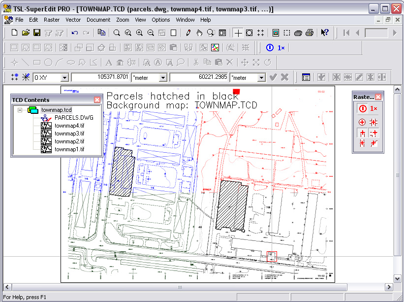
Start SuperEdit by double-clicking its icon that was created by Setup. In the File Open dialog choose File Type TCD and open the file townmap.tcd from the SuperEdit’s DOC subdirectory. You should see the SuperEdit screen layout, as in the figure below.
The content of the townmap.tcd document, consisting of four raster images, is presented graphically in the right part of the SuperEdit window, named Drawing window. The left part, named TCD Contents window, displays the structure of the document, with townmap.tcd as a root node and with four sub-nodes townmap1.tif, townmap2.tif, townmap3.tif, townmap4.tif that correspond to individual raster images. You may easily identify which node corresponds to which raster image by double clicking at the small bitmap picture displayed near each node name, thus selecting or de-selecting appropriate raster image. Selected nodes have their names displayed using bold font. Selected raster images are presented with thin black frame with small black handles displayed around its extents.
The TCD Contents window is displayed only if you work with Tessel Composite Documents. When working with simple raster or vector drawings, SuperEdit acts like single-drawing editor.
In the upper part of the main window, SuperEdit displays several toolbars with buttons and other controls. The first one, named Main toolbar, contains most common and general options, like New / Open / Save document buttons, general Undo / Redo buttons, various Zoom buttons, other buttons specific to whole composite document like Select or Views, section of Print supporting buttons and Help buttons. The Raster toolbar contains buttons with various raster-editing commands; they are active if some raster drawings are selected. The Vector toolbar’s buttons allow creating, modifying and manipulating vector entities in the current foreground vector drawing, if one exists. Other specific toolbars facilitate performing more complicated actions, e.g. calibration.
You can see the name of each toolbar button in a ToolTip. When you point to a button with the mouse cursor for a longer while, the button’s name will appear in a box. We will use those names while referring to the buttons later in this manual. You can find more descriptive explanation of the button’s action in their hints displayed in the status line.
Depending on the status of SuperEdit session some of the buttons may be inactive and displayed with grayed faces.
One of toolbars has two edit boxes with numerical coordinates. This is the Input bar. You can read position of the mouse cursor in the Drawing window from there and enter desired values in various drafting operations. The position is displayed in terms of world coordinates; you may control the coordinate system and the presentation units, using appropriate combo boxes of the Input bar.
If you cannot find some toolbars, it is possible that somebody has turned them off. Use appropriate option from the View menu to switch it on.
All commands available from toolbar buttons may be accessed from main window menu, as well. All SuperEdit commands are organized in several topics according to MS Windows style; in addition to well-known File, Edit, View, Window and Help standard topics you will find topics specific to SuperEdit functionality like Raster, Vector, Document and Zoom. Please read chapter 6 for detailed description of main menu structure and complete explanation of all SuperEdit commands.
To facilitate instant access to manipulate on different objects and to enhance support for more complicated operations SuperEdit uses pop-up menus. They are activated by right mouse button click into some object or some window. Three kind of pop-up menus may be distinguished:
Composite Document pop-up menu (CDM) that is displayed after right click into specific node of document tree, displayed in the window. The set of options shown depends on the node type;
Drawing Window pop-up menu (DWM) that is displayed after right click into Drawing window, but only if foreground vector drawing is presented there. The set of options depends on the state of selection of vector entities contained in the foreground drawing;
Options and Tools pop-up menu (OTM) that is displayed during more complicated commands performed in Drawing window, to give you access to various commands’ options and other tools (like raster snaps). Sometimes OTM is displayed automatically when you are supposed to complete the command by necessary decisions.
To make description of various actions shorter, common notation like e.g. “CDM Disable”, “DWM Select” or “OTM Accept” will be used to describe options accessible from appropriate menu after activating it using right mouse button click.
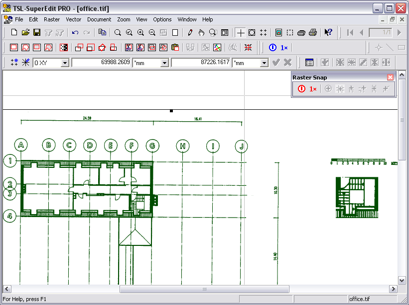
The most fundamental function of SuperEdit is to enable viewing of full-size scanned drawings in its Drawing window. The viewing function enable zooming and scrolling so all details of drawings can be inspected.
Start SuperEdit by double-clicking its icon that was created by Setup. The File Open dialog appears automatically after start. You should see the SuperEdit screen layout, as in the figure below.

Choose File Type TIFF and open the file office.tif from the SuperEdit’s DOC subdirectory. The image will get opened and, because of default configuration options, it will be automatically zoomed to its full extents and selected for editing. All buttons of the Main toolbar, except of Save, Scan one, Scan many, Undo and Redo, should be active, and its status line should read office.tif. All buttons of the Raster toolbar should be active (except Merge that requires more than one raster image being selected).
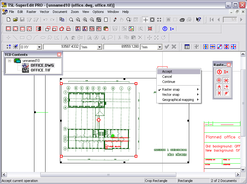
Move the SuperEdit cursor around to see that its coordinates are displayed in Input bar X and Y boxes. They would make sense for a building floor measured in millimeters and this kind of units is displayed in Input bar. This results from the values of parameters that have been set for the office.tif image. Enter Image Properties... option from Document menu. Since the program knows that you open a single file, this button will directly show parameters of the only raster image that is opened at the time, as in the figure below.
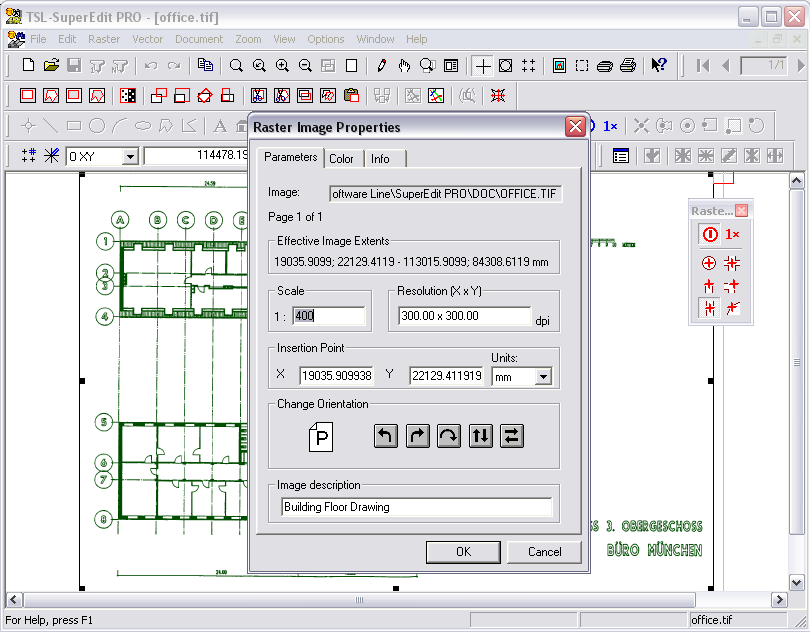
The Parameters tab of the Raster Image Properties dialog shows the full path to the image file, Effective Image Extents in the current Units (mm), the nominal Scale (1:400) and Resolution (300×300) and the Insertion Point coordinates. All those parameters make it possible for SuperEdit to place the image in the world coordinates system, so that it may be compatible with overlaid drawings. Close the Raster Image Properties dialog.
Use Zoom command (from Main toolbar or Zoom menu) to view different parts of the scanned drawing. All SuperEdit commands are available from some kind of toolbar or menu. Use them in a way you find more convenient.
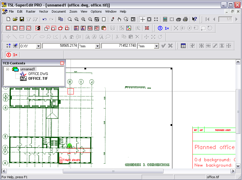
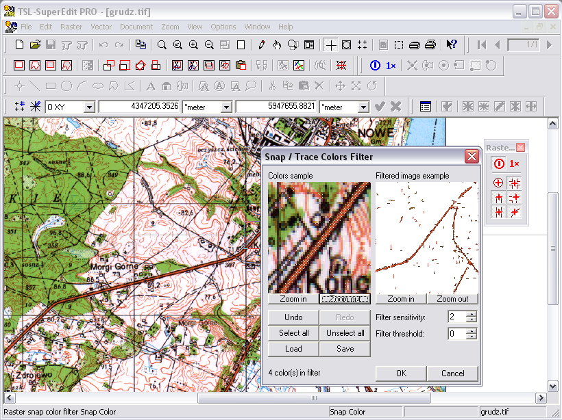
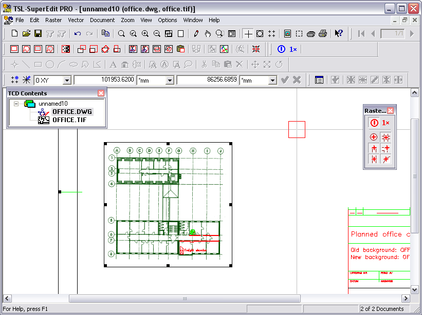
While having the scanned drawing office.tif opened (see the previous section), click Switch to TCD Mode option from the Document menu to display the TCD Contents window presenting the structure of the composite document. Click the root TCD node using the right mouse button to show the Composite Document pop-up menu (CDM) and choose the CDM Add Subdocument option in the CDM pop-up menu that appears. Choose office.dwg vector drawing from the SuperEdit’s DOC subdirectory.
SuperEdit should show a DWG with a complete drawing border, some walls, doors and other objects drawn over the scanned background. If you don’t see the entire drawing, as shown in the figure below, use the Zoom Extents button.
The new walls and doors are meant to replace the old ones that must be removed from the raster image. In order to see how this should look like when done, use the CDM Add Subdocument option as described before and choose office2.tif from the SuperEdit’s DOC subdirectory. Right-click the office.tif node in the TCD Contents window and choose the CDM Remove option.
Whenever you need, e.g. for the reasons of the graphics screen clarity, to take some drawing temporarily off the screen, simply choose the CDM Disable option. The option changes to CDM Enable, so that you can bring the background image back, when you need it there.
The combination of office.dwg and office2.tif makes up a hybrid document that shows the intended modifications of the building floor. Both raster and vector components of the hybrid drawing may be printed together. The next section describes how to get the modified office2.tif.
SuperEdit provides tools to control and modify raster images. You can use the Image Properties dialog (called from CDM Properties option) and its subcommands to modify various parameters of the raster image. The Move command changes image insertion point (origin). The Clear command clears chosen rectangular or polygonal areas of raster images. Other raster editing commands are: Crop, Filter, Rotate, Resize, Cut, Copy, Paste, Merge and Calibrate. All raster-editing commands can be accessed from Raster toolbar or from main Raster menu.
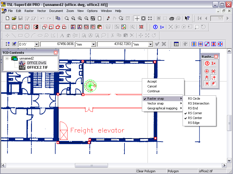
As at the beginning of the previous section, open the office.tif, and then use Document - Add Subdocument option to add office.dwg vector drawing. Use Zoom Window button to show the right lower corner of the floor, where the new walls and doors have been drawn. To define a zoom area, move mouse cursor in its one corner, press the left mouse button and drag the cursor to the other corner of the area you want to zoom, then release the button.
Click the Clear polygon button in the Raster toolbar and define a polygon that fences around those parts of the background drawing that need to be removed, as shown in the figure below. Define subsequent vertices using left mouse button clicks. Choose OTM End polygon option that ends drawing a polygon (you may choose OTM Step back to go back to previous vertices). If you need to redefine one or more vertices after finishing the polygon, simply drag their red grips to desired positions. To stop entering subsequent polygons, click the right mouse button once more and choose the OTM Accept option.
SuperEdit edits the image file and regenerates the screen. Click the Undo button on the Main toolbar to see the office.tif before the modification. Then, click the Redo button to see the modified drawing again. Right-click the office.tif node in the TCD Contents window, and choose the CDM Save As... option. Save the modified image under a new name, e.g. office3.tif.
SuperEdit’s composite document viewer supports a number of raster formats (see the section called “Appendices”) including full-color pictures, e.g. photographs. Similarly to monochrome scanned images, color pictures may be equally well assigned the scale and other parameters that define the image position in the world coordinates system.
Click the Open button on the Main toolbar. For File Type choose TIFF and open the photo.tif file in the DOC subdirectory. Click the Image Properties button on the Main toolbar and inspect the parameters in the Raster Image Properties dialog, as in the figure below.

The Effective Image Extents of the photograph in the SuperEdit drawing window result from the Scale (1:300), Resolution (110x110 dpi), Units (mm) and the Insertion Point (0.0, 0.0 mm). Please try to change those parameters in the Raster Image Properties dialog, close it and, after the regeneration ends, check how they affect the extents of the image on the graphics screen.
The color image can be moved, i.e. its origin changed, interactively on the graphics screen. The origin is by default defined in the lower, left corner of raster frame. Click the Move button on the Raster toolbar. Notice the default origin symbol, drawn in gray color, placed exactly in the lower left corner of the raster frame. You may click the Zoom Out button on the Main toolbar to look at the whole operation from greater distance. A new origin position, drawn in yellow color, moves under the cursor. Click at a point on the image for which you want to define new coordinates, leaving the yellow Base point there. Now a new destination position drawn in red color moves under the cursor, so you can drag the whole raster frame. Click where that point should be moved to on the screen, leaving the red Target point there. Use the OTM Accept option to move and regenerate the image at the new position. To move it back, click the Undo button on the Main toolbar.
You may enter the coordinates numerically. Click the Move button again. Instead of showing the base and target points with the cursor, type:
Tab 2500 Tab 6700 Enter - for base point
Tab 0 Tab 0 Enter - for target point
(First Tab moves your input to the X box, second Tab – to the Y box, while Enter accepts both entered values). The frame of the image is moved to the expected new position. As previously, choose the OTM Accept option to move and regenerate the image at the new position.
SuperEdit’s capability of handling composite documents is useful while comparing different versions made of the same raster image.
Click the Open button on the Main toolbar, for File Type choose Tessel Composite Doc (TCD), and open the electric.tcd document in the DOC subdirectory. The document should appear in the Drawing window as a scanned electrical drawing in blue, with a few red lines. In the TCD Contents window, the structure of electric.tcd document is displayed. You can see that there are two subdocuments: electric.tif and electnew.tif in the composite document. On the SuperEdit’stitle bar, you should see the same information in the form: electric.tcd (electric.tif, electnew.tif). In order to find more detailed information, choose the CDM Properties option for the electric.tif node. You should see Parameters dialog of this image. Click the Color tab to see the tab that defines the presentation color for this monochrome raster image: 5-blue. Click Cancel to close the Raster Image Properties dialog. Check this color for electnew.tif subdocument. Notice that it is: 1-red, as shown in the figure below.

Choose the CDM Properties option for the root electric.tcd node. When the Composite Document dialog pops up, click at the second entry on the Subdocuments list, so that electnew.tif is highlighted. Then click the Bring forward button on the right side of the Subdocuments list, so that this drawing’s entry moves to the top of the list. Click the Close button to close the Composite Document dialog and to regenerate the view of the composite document according to the new order of subdocuments (observe the change of succession in the TCD Contents window, too). The color of the image on the screen will turn red, as the red electnew.tif is now covering most of the blue electric.tif, except of the small part that has been deleted from electnew.tif and remains visible in blue.
Notice that the Raster toolbar buttons are grayed. Double-click the electnew.tif node on TCD Contents window using the left mouse button, to select it (or choose the CDM Select option). The name of the node electnew.tif in TCD Contents window becomes bold. SuperEdit displays thin, black frame with rectangular tracker marks at their corners and midpoints around raster image in Drawing window; the frame shows extents of the selected image. Notice that the Raster toolbar buttons become active. We say that the image is selected, so that it is ready for editing.
Click the Clear rectangle button on the Raster toolbar and choose a rectangular area of the red image to be cleared. Click the left mouse button in one corner; move the mouse cursor and click the other corner to define the rectangle. Accept the clearing operation by OTM Accept option and watch as another part of the blue image underneath gets uncovered. Close SuperEdit without saving the changes made to the electric.tcd document, which also cancels all changes made to the subdocuments.
As we have shown in the previous section, SuperEdit can operate on composite documents that consist of a number of subdocuments. A composite document itself may be seen as a list of links (path names) to files that contain raster or, optionally, vector drawings.
In order to create a sample composite document, start SuperEdit, cancel the File Open dialog and click the New button on the Main toolbar. SuperEdit displays the TCD Contents window with the only root node named unnamed1 and the empty Drawing window. Choose the CDM Add Subdocument option for the root node. Choose the SuperEdit’s DOC subdirectory and the File Type TIFF in the Add Document File(s) dialog; select four files townmap1.tif ... townmap4.tif and click the Open button. The selected files are to be placed below the root node; watch the TCD Contents window content to assure that they really are. The Drawing window will be regenerated to show four parts of image. You can also click Image properties button on Main toolbar (or choose the CDM Properties option for the root node) and inspect Composite Document dialog as shown in the figure below.

The composite document inherits its Units from the first added subdocument’s TAF attribute file (townmap1.taf), and its Common Extents represent the combined area of all subdocuments.
Click the Save button on the Main toolbar and save the unnamed1 composite document as map.tcd, so that the existing townmap.tcd is not overwritten.
In the preceding sections we were modifying single raster images that were selected for editing operations automatically, as the Auto select single file documents configuration option has been checked. Whenever SuperEdit operates on a multi-file composite document, the subdocuments to be affected by the editing operations must be selected by the user.
Click the Open button on the Main toolbar, for File Type choose Tessel Composite Doc (TCD), and open the townmap.tcd document in the DOC subdirectory. Note that Raster toolbar consisting of raster editing buttons, like Clear, Move, etc., is disabled (grayed).
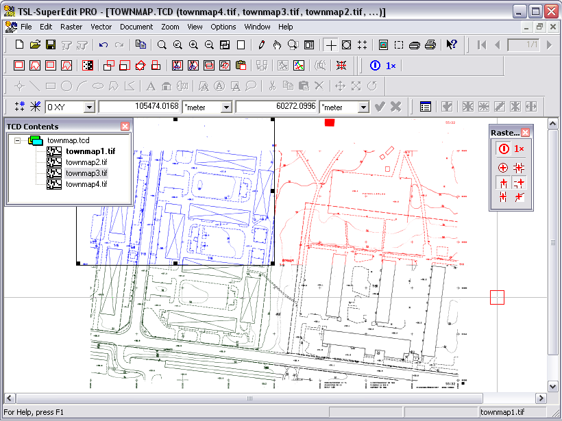
Select townmap1.tif by double clicking the townmap1.tif name on TCD Contents window using the left mouse button. Repeat the action with townmap4.tif. The names of the selected nodes in TCD Contents window become bold. The selected subdocuments in Drawing window will be marked by the rectangles of their viewports drawn with rectangular tracker marks at their corners and midpoints. You should see the SuperEdit window as shown in the figure above.
Double click the townmap3.tif name on TCD Contents window and then double click it again. Notice that the second double click deselects townmap3.tif.
If you want to check the selection status on the Subdocuments list, or it is more convenient to do the selection there, click the Image properties button on Main toolbar. The Composite Document dialog will show the two selected entries of the Subdocuments list, townmap4.tif and townmap1.tif, preceded by the S selection mark and displayed in red, as shown in the next figure.

You may combine both methods of selecting:
structural - clicking nodes on TCD Contents window;
from the list - using the Image Properties button, highlighting the drawings on the Subdocumentslist and clicking the Select and Unselect buttons in the Composite Document dialog.
Close the Composite Document dialog, click the Clear rectangle button on the Raster toolbar. Define a large rectangle around the center of the map, so that it includes portions of all four (4) segments of the map. Use the right click to display the pop-up menu and choose OTM Accept option to accept the clearing operation. After the image regenerates, you should see that the editing operation has affected only the two (2) selected images, leaving the others unchanged.
Click the Undo button on the Main toolbar. The last editing step will be cancelled for both selected images. Double click the both images on TCD Contents window. SuperEdit will return to the nothing-selected state and the Raster toolbar will be disabled (grayed).
Keeping subdocuments in separate image files and having them logically connected in a single TCD document is a recommended way of working and should be used whenever possible. Sometimes however, a need may arise to merge selected subdocuments into a single raster file, e.g. in order to make the combined images available to applications that do not support composite documents.
Open townmap.tcd and select two subdocuments, as described in the previous section on Selecting and controlling subdocuments. Click the Merge rasters button on the Raster toolbar and type a new file name, e.g. maps1&4.tif, for the merged file in the Merge selected images to dialog box that pops up on the screen. After having the merge operation completed, open the newly created file. It should contain the selected subdocuments merged into one file, as shown below.
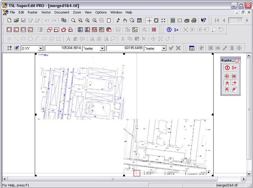
The Merge rasters command is particularly useful when merging a larger number of subdocuments selected from a complex TCD file with dozens or even hundreds of subdocument links. Each subdocument preserves its position in the world coordinates system, so, if the source subdocuments were calibrated, the merged result will be equally well calibrated without any additional actions.
SuperEdit provides editing tools for vector drawings in Tessel Vector Document (TVD) format with structural capabilities similar to other popular drafting systems.
Several basic types of vector drawing entities are supported by SuperEdit vector drawings. You can define geometrical entities like segments, polylines, polygons, rectangles and circles. You may write single or multi-line texts using individual fonts and various predefined framing styles. You can place bitmap icons in various scales, referring them to raster files of any format.
Drawings imported from DXF vector drawing files may contain definitions of blocks with their own list of entities. The entity that refers to the block definition and displays its entities with individual insertion point, scale and rotation is called an insert.
Several entities of any type may be grouped together, creating complex entity. It gives you the possibility of organizing vector entities in hierarchical structure, where several entities may be treated as single one.
There are some predefined types of simple and complex special entities used in dedicated contexts. They will be described separately.
Vector drawing entities can be drawn with various line styles (solid, dashed, dotted, etc.), line width, line color, as well as with various fill styles (none, solid or hatched) and fill color. (Windows renders line styles only when the thickness value equals 0). Vector entities may be drawn as opaque or transparent. You can use Windows bitmap hatches and/or SuperEdit scalable hatches that are called patterns. All these features are referred as drawing tools. You may set current general drawing tools, used as default during creation of new entities. You may change individual tools per each entity independently as well.
Each entity in the vector database may have list of various user-defined, numerical (integer or double) or string data attributes assigned to it. Each attribute has a unique string key. Numerical attributes may have attached an action that can be addition, subtraction or skipping. The key is used as an index and can be supplied by the external database or defined by you. The action defines the rule of the attribute value computation up to the top of the entities’ hierarchy.
Vector drawing entities may be placed on different layers in the vector drawing. Some layers are created automatically, e.g. standard layer “0”. You may create your own layers with individual names. Each layer has its own visibility and activity attributes. Entities placed on layer that is not visible are not displayed – so they are invisible. Entities placed on layer that is not active are displayed, but can not be selected – so they can not be edited and deleted. One layer can be declared as current. All new created entities are placed on the current layer. By default the standard layer “0” is current after creating a new vector drawing.
To facilitate creating various texts with uniform layout, the text style concept is used. Text style defines the Windows font used for drawing text, as well as its other characteristics, like default height, aspect ratio and escapement angle. Various border styles used for framed texts are supported as well. Individual texts derive these parameters from the style they refer to; however, their individual values may be changed for each text independently.
For your convenience, some basic text styles are created automatically. You may create your own text styles with individual characteristics and store them together with whole vector drawing.
To facilitate creating various hatches with uniform layout, the pattern concept is used. Pattern has its unique name and defines such parameters as distance between lines, line thickness, angle and color of each line as well as its style and crossing parameter. (Windows renders line styles only when the thickness value equals 0). The crossing parameter controls drawing of the perpendicular set of lines. Individual hatches derive these parameters from the pattern they refer to; however, their individual values may be changed for each hatch independently.
For your convenience, some basic patterns are created automatically. Your may create your own patterns with individual characteristics and store them together with whole vector drawing.
New version of vector drawing library has a full capability of defining separate block lists in vector drawing. Block definitions list vector entities that may be easily referenced from special vector entities called inserts, each one with individual insertion point, scale and rotation angle. Insert entity does not duplicate all entities from block definition, but displays them and allow to snap to them as if they were "inserted" in given position, scale and rotation. Changing the block definition updates all inserts from which it is referenced automatically.
You may examine the list of all block definitions in the vector drawing and preview each block from the Blocks page on the Drawing properties dialog.
Drafting on the background of scanned drawings may be one of the most natural applications for SuperEdit. As the background documents can be properly mapped into the world coordinates system, it is possible to work using normal dimensions and standard symbol libraries.
Vector drawings in DWG, DXF or HPGL formats are displayed in the background, similarly as raster drawings, either as single drawings or as subdocuments of a composite document. Only drawings stored in Tessel Vector Drawing (TVD) format can be marked as foreground ones by selecting only one of them, and may be manipulated and edited.
Click the Open button on the Main toolbar, for File Type choose Tessel Composite Doc (TCD), and open the townmap.tcd document in the DOC subdirectory. Then, right-click the townmap.tcd node and choose CDM Add Subdocument option. Choose the parcels.dwg drawing in the DOC subdirectory. The DWG drawing shows two hatched polygons and a text informing that its background map is a composite document townmap.tcd.
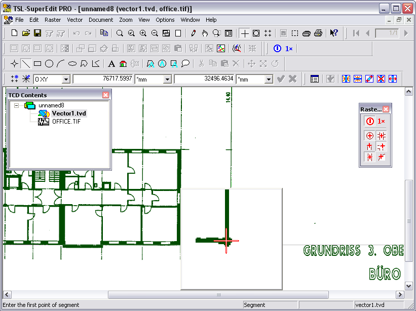
Then, choose the CDM Add New Vector option for the townmap.tcd node. A new empty vector drawing named vector.tvd is added as a subdocument. SuperEdit selects automatically the new vector drawing placing it in the foreground, which is marked by the pencil symbol placed across the icon representing the new vector node.
Notice that the Vector toolbar becomes enabled. Double-click the vector.tvd node to deselect it. You can notice the pencil symbol disappears and the Vector toolbar becomes disabled. This is because the new vector drawing after deselecting is moved to the background. Double-click the vector.tvd node to select it back and moving the vector.tvd to foreground again, thus enabling drafting in this drawing. Having several TVD vector drawings in the composite document, you may activate chosen one for editing by selecting it and thus moving it to the foreground. However, you have to select exactly one vector drawing to declare it as a foreground one; this is to avoid unnecessary conflicts about which drawing is active when more than one are selected in the same time.
Let us define texts and polygons that similar to those in the DWG background drawing. We will try to do it exercising some basic methods to interact with SuperEdit drafting interface.
Click the Text button on the Vector toolbar and in the Content box on the Text Properties dialog write down the first line text from DWG drawing. Choose Style tab on the dialog and select the COURIER style in the style name combo-box; it will give the best match to the AutoCAD’s style used in the DWG drawing. Click the OK button and drag the cursor to the place of the background DWG text. First click defines the lower left corner of the text frame; next determine the text’s height. After defining the text, it is ready for correcting, if necessary. Dragging the red grip placed in its left lower corner moves the text frame. Using the right upper grip, you may match the size of the text frame to the background DWG text size. Repeat the action with the second line text.
Zoom the area with the background polygon. Then click the Polygon button on the Vector toolbar and define a polygon that matches the original one (left mouse clicks enters subsequent vertices, the OTM End polygon option ends drawing a polygon). After defining the polygon, it is ready for correcting. Simply drag the red grips to corrected positions, if necessary. If you move the cursor over one of the polygon’s edges, you can see its shape changes to a star. It means that you may add vertex starting from this place. Simply press the left mouse button and drag new vertex to desired position. If you want to delete some vertex, move the cursor over that vertex until it changes its shape to an arrow and choose OTM Delete vertex option in the menu that appears after clicking the right mouse button.
Since the new polygon is selected, the options displayed in the pop-up menu that appears after right-click anywhere into the Drawing window area (Drawing Window menu – DWM) are concerned with the entity selected. Examine DWM options like DWM Transform, DWM Copy, DWM Delete etc., some of them with various sub-options. The DWM Properties... option displays the Polygon Properties dialog; you may examine and change numerical coordinates of the polygon’s vertices in the appropriate boxes on the Polygon tab. You may call DWM by right clicking anywhere on the Drawing window; these clicks do not change the selection.
Now perform left click somewhere outside the polygon; its red grips disappear and it becomes deselected. Examine DWM options now, concerned with the whole foreground vector drawing only. The DWM Properties... option displays now the Drawing properties dialog; you may examine vector drawing extents and change vector drawing units on the General tab (make sure that the drawing units are meter).
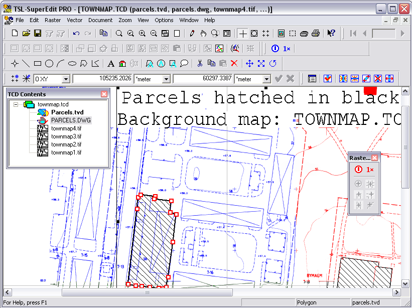
Now perform left click inside the polygon or near its edge; it becomes selected again. Choose DWM Properties... option to display the Polygon Properties dialog, and select the Tools tab. Enter Line Thickness: 0.8, Pattern Name: FORWARD DIAGONAL, Pattern Distance: 2.5 and then OK button. Repeat the action with the second polygon.
Click the Image properties button on the Main toolbar in order to see Composite Document dialog. At this time, you should see a vector.tvd reference to the TVD drawing added to the list of subdocuments. The S and F flags denoting that it is selected and foreground should precede its pathname. Click the Save As... button on the dialog and save the TVD drawing as parcels.tvd. Close the Composite Document dialog. The same action could be performed in the TCD Contents window by choosing the CDM Save As... option for the unsaved vector.tvd node.
In the TCD Contents window, choose the CDM Disable option for the parcels.dwg node.You should see the picture as below.
Choose the CDM Enable option to see it again. Use the File - Save As... option and save the modified composite document as estate.tcd.
Close the SuperEdit session and start the program again. Click the Open button on the Main toolbar and open the newly created estate.tcd.
Note that parcels.tvd is automatically selected and opened for foreground editing by SuperEdit. The background is provided by the remaining subdocuments of estate.tcd, i.e. parcels.dwg and townmap4.tif, ..., townmap1.tif.
SuperEdit’s Magnifying Glass tool provides quick and transparent access to a detailed view of the raster image in the neighborhood of the current cursor position. Magnifying Glass is an important support tool for snap to raster functions, as described in the next section of this manual. It is, however, very useful also independently from snapping and may be used for quick viewing of image details and precise manual positioning of the cursor on the raster image while executing SuperEdit commands.
Click the Open button on the Main toolbar, for File Type choose TIFF, and open the office.tif drawing in the DOC subdirectory. Choose the Options - Configuration option and select the Magnifying Glass tab. Check the Magnifying Glass active and Pop up on hot key pressed options - this will let you pop up Magnifying Glass by clicking Ctrl+Q. Default values for Size (100 pixels) and Magnification (3 times) should do fine for most images, but of course, you may change them as needed. Sometime it may be wise to change the Magnifying glass hot key to something else then Ctrl+Q, say F12.

Choose Document - Add New Vector option to add empty vector.tvd drawing and to enable the Vector toolbar. Use Polygon button to draw an outline of the scanned floor drawing, or to connect any specific points of it. This practically forces you to use Zoom Window and Zoom Extents commands repeatedly, which is certainly not convenient.
Now repeat the same exercise using Magnifying Glass. Click the Zoom Extents button on the Main toolbar to show the entire document. Click the Polygon button on the Vector toolbar and place the cursor near the intended position on the raster image. Hit the Ctrl+Q key (Magnifying glass hot key). The Magnifying Glass pops up showing an enlarged neighborhood of the cursor position, and a cross cursor that you may use to define a point within the Magnifying Glass window.

Place the cross cursor precisely on the enlarged raster image and click the left mouse button to define a point. The Polygon command receives the point’s coordinates, the Magnifying Glass window disappears, and you may proceed to define next point. Please notice that you may close the Magnifying Glass window without defining a point simply by moving the mouse cursor outside of it.

Magnifying Glass is equally usable while defining those SuperEdit commands that require precise graphical input. Zoom Window to show the lower half of the office.tif image. Click the Clear button on the Raster toolbar. Try to clear interiors of rooms located next to the stairs. It is much easier to define rectangle or polygon corners when you hit Ctrl+Q and define each point through Magnifying Glass.
If you want to remove Magnifying Glass from the screen, simply move the cursor away from it and it disappears. However, if the Keep on display option on the Magnifying Glass tab in the Configuration dialog is checked, you must accept each point entered using right mouse button click or press Esc to close Magnifying Glass without defining a point.
When you need to have a better control over the exact position of points that are being entered through Magnifying Glass, check the Keep on display option on the Magnifying glass tab of the SuperEdit’s Configuration dialog. This will make the Magnifying Glass pop up window wait on the screen until you click the right button to accept the entered point position. Press Esc to close Magnifying Glass without defining a point.
Drafting on the background of scanned images can be made more convenient and productive with help of SuperEdit’s selective Raster snap function. Snapping to raster features may be enabled permanently or transparently called from within SuperEdit commands.
Open the office.tif image as described previously. Choose the Options - Configuration option and select the Snap tab. Check the Snap to raster active option and the following Snap modes: Intersection of raster lines and Corner of raster line. Increase Pickbox size to 20, or so. Make sure that the Magnifying Glass options Verify every snap trial and Keep on display are checked. Click the OK button. The Raster snap pickbox will be added to the cursor, indicating that the continuous snap to raster mode is active.

Use the Document - Add New Vector option to add empty vector.tvd drawing and to enable the Vector toolbar. Use Segment button to draw the segment overlapping a vertical dimension line labeled 13.28. Place the pickbox around one end tick of that vertical dimension line and enter the point by the left mouse click. Magnifying Glass window pops up to show the result of snap to the intersection point. If the position of the snapping cross is correct, accept it by clicking the right mouse button. Otherwise, place the cursor correctly inside the Magnifying Glass window and click the left mouse button. Accept the adjusted position by right click.
Repeat the same action for the other end of the dimension line.
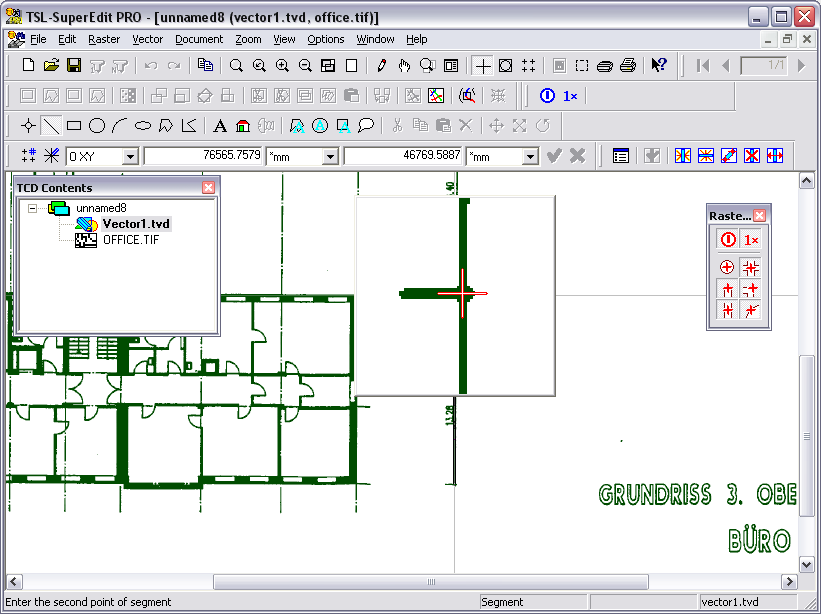
Then use the DWM Properties... option. On Measurement tab of Segment Properties dialog read the length of the segment.
The measured length is 14362.4562 (mm), quite different from the 13.28 (m). You will get much better result when using office4.tif that you may have created doing the resizing or matching exercise described in sections below.
The usability of various snap modes depends heavily on the features of background raster images. It is recommended to use the Magnifying Glass to verify snap results visually and to correct it manually, whenever the automatic snap result is not satisfying.
Lines and other entities of color images can be made of many colors in different shades, so some kind of filtering scheme is needed in order to let the snapping mechanism properly determine the boundaries or raster lines and areas. SuperEdit offers an interactive Raster snap color filter tool that lets the user define and examine adequate color interpretation, before it is used for snapping purposes.
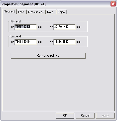
Open the grudz.tif image, a color map that contains some features, like roads and forest areas, suitable for color-sensitive snapping. Choose the Options - Snap colors... option. Enter a point nearby area containing a junction of main roads that drawn in red. The Snap / Trace Colors Filter dialog shows two windows, Colors sample and Filtered image example, that allow for further zooming in and out, if necessary.
In the Colors sample window click those pixels in different shades of red that belong to the main road line. All pixels of the same color get marked by white dots, the counter of Colors in filter increments, and the Filtered image example window shows the filtered image; clicking inside this window toggles between color and black and white presentation. Clicking once more at a selected pixel in the Colors sample window removes its color from the filter; you may also use additional control buttons.
After having a color filter defined, click the OK button to close the Snap / Trace Colors Filter dialog, then choose the Options - Configuration option and select Snap and Magnifying Glass options. Use the Document - Add New Vector option to add empty vector.tvd drawing and to enable the Vector toolbar. Use the Polyline button to draw the polyline along the road. Try snapping to different features, the centerline or intersection of the roads, or the edge of the forest areas.

Scanned grudz.tif is a full color image, so a good filter definition for the main roads may require up to 12 colors. The forest areas drawn in various shades of green, may take more than 20 colors, possibly collected from a number of samples. Needless to say, your snapping results will be only as good as the colors filter’s ability to retrieve a complete image of interesting entities, and only those, from the image. Furthermore, some color images will simply not contain any suitable entities to snap.
Filter colors selections may be saved and loaded when needed again using Save and Load buttons in the Snap / Trace Colors Filter dialog.
Cropping may be the most common raster editing operation, as the scanned images usually contain oversized margins, usually filled with dirt, that need to be cut off. Equally often you might need to remove old drawing borders and other parts that happened to be located closer to drawing’s margins.
Open the office.tif rasterimage and then choose Document - Add Subdocument option to add the office.dwg vector drawing.
Suppose that the only part of the scanned drawing that you need for your project is the floor shown between dimensioning lines. Texts on the right side may be removed and the scanned image extents may be actually smaller.
Click the Crop rectangle button on the Raster toolbar. Define a rectangle encompassing this part of the scanned drawing that you want to have and accept the command by the OTM Accept option. The picture below shows situation just before the acceptance.
All unwanted parts are cut off and the scanned image will get smaller, as shown below.
Click the Undo button on the Main toolbar to reverse the changes, or exit SuperEdit without saving anything.
In one of previous exercises we have used the background of office.tif in order to create a new design by clearing some unwanted areas. The resolution, scale and orientation of the background image were correctly defined, but the original drawing may be not to the scale and the scanning process may have produced a skewed image with distorted size and proportions.
Open the office.tif rasterimage and then choose Document - Add Subdocument option to add the office2.dwg. This vector drawing contains a polygon drawn to the nominal dimensions of an office building. You will easily see the difference between vector-defined outline and the corresponding scanned image, as shown in the figure below.
You may repeat exercises made in chapter describing raster snaps to check that the distances on the scanned image are not according to horizontal and vertical dimensions that are shown on the image. If the scanned image is needed as a background for any kind of precision drafting, it must be dimensionally matched to its reference dimensions, and that may require independent X & Y resizing.

Before we resize the image, however, it is recommended that the scanned image be aligned either horizontally or vertically. In the exercise we will use Magnifying Glass, so choose the Options - Configuration option and check on the Magnifying Glass tab the Magnifying Glass active, Pop up on hot key pressed and Keep on display options. It would be wise to define F12 as Current hot key - simply select it in its box and press F12.
Make sure that office.tif is selected for editing. Click the Rotate Raster button on the Raster toolbar. In order to align the whole image, so that the left wall is vertical, define two points at its edge.
The process of defining rotating operation starts from the Define base point phase, as can be read from the hint displayed in the Status line. The base point symbol, drawn in yellow color, moves under the cursor. Place the cursor at the outside edge near the left lower corner of the building. Hit F12 (Magnifying glass hot key) to pop up Magnifying Glass. Click exactly at the wall’s edge. If the picked point position looks good, accept it with a right click. The yellow symbol of the base point becomes placed in this position.
Now comes the Define endpoint of the reference vector phase. The reference vector, drawn in yellow color, is dragged by its end marked with an arrow. Place the cursor near the left upper corner of the building and repeat the action as previously. The yellow reference vector is placed along the left edge of the building.
The last phase, Define endpoint of the rotating vector, finally defines the rotating operation. Notice the rotating vector drawn in red color. You can observe the effect of rotation being defined, shown by rotated raster frame, and the rotation angle displayed numerically in the Input bar. Since we want to define alignment, not rotation, call Options and tools menu (OTM) with right click and choose the OTM Vertical option, then use the OTM Accept option for the whole alignment.
Wait until the raster is rotated and the Drawing window regenerates the image. The visible effect of alignment will be rather small, as the image was skewed only a little, but you may notice that some horizontal and vertical raster edges are now sharper. Save the aligned raster image as office4.tif.
Next, we will move the raster image, so that its left lower corner corresponds to the left lower corner of the reference vector data. Define zoom window around the left lower part of the building as follows. Move the cursor to the one corner of the area to be zoomed. Press and hold the left mouse button, dragging the window up to its opposite corner. Then leave the button to regenerate the image as shown in the figure below.

Click the Move raster button on the Raster toolbar. Use the Magnifying Glass as before to place yellow base point exactly at the intersection of reference lines at the left lower corner of the building. Repeat the action to place red symbol of the target point exactly at the left lower corner of vector reference polygon visible on the office2.dwg drawing. Choose the OTM Accept option; the left lower corner of the building’s wall should move to the desired position. If you are not satisfied with the result, click the Undo button on the Raster toolbar and repeat the Move raster operation.
The scanned image, now aligned and moved to the correct position, is apparently too large comparing with its reference vector data. Click the Resize raster button on Raster toolbar. The process of defining resizing operation consists of three phases, similar to those in rotating action: Define base point phase, Define endpoint of reference vector phase, and finally Define endpoint of resizing vector phase.
The left lower corner is at the correct position already, so we will use it as base point - its position will be not changed by the Resize operation. Place it using the Magnifying Glass as before at the left lower corner of vector reference polygon again, this time as the easiest way of defining base point that we have moved there previously. To define the endpoint of reference vector, scroll the Drawing window to show the right upper part of the building. Use the Magnifying Glass and click exactly at the intersection of reference lines in the right upper corner of the image (just under the J in a circle sign).
In the final step, define the endpoint of the resizing vector using Magnifying glass and place it at the right upper corner of vector reference polygon.

Choose the OTM Accept option for the whole resizing operation. After resizing the scanned image should quite exactly match its vector reference data, so that further drafting on its background may be done directly in world coordinates.
Click the Save button on Main toolbar.
The matching procedure described in the previous section is quite simple to understand but not so simple to execute, since it involves a number of steps, like Rotate, Move and Resize, which are needed to achieve desired results. Providing that we have sufficient reference data, the same and even better results may be achieved using the simplest possible interface to powerful Tessel Systems CALIBRATOR.
As in the previous section, open office.tif and add office2.dwg. We want to get the best possible match between the four corners of the vector reference polygon and the corresponding corners of the raster image.
Click the Zoom extents button on the Main toolbar. Click the Calibrate raster button on the Raster toolbar. Since the calibrating action has many options and may involve some additional actions required in its full version, special Calibration toolbar pops up just over the Drawing window. In its basic version exercised below, we will define four matching vectors supplying data required for simplest match. For each corner of the scanned floor drawing define raster point by placing the cursor close to the corner, pressing F12 (Magnifying Glass hot key) and picking the intersection of reference lines at that corner, as shown below.

Accept raster point by a right click, move the cursor to the corresponding corner of the vector reference polygon and use Magnifying Glass again to show its exact position as end of matching vector (target point).

After defining matching vectors for all four corners, click the Affine model button (second one among five buttons defining various models) on Calibration toolbar. You may also click the Toggle preview button, to watch the way the raster image would be modified to fulfill matching requirements. Use the OTM Execute option and, after the raster image is recalculated, use the OTM Accept option to finish the whole action. Say No when SuperEdit asks you to save calibration report and changes to vector list, it is not necessary in this case. After the raster image is recalculated, you should be able to see that this simple and quick operation has produced quite a perfect match at all four corners. To check what such simple to do a matching operation is worth, repeat the exercise from the chapter describing raster snaps trying to measure the actual length of the vertical dimension line described with dimensioning text that says 13.28.
Instead of previous measurement of 14.36, you should obtain something like 13.26. Definitely not bad a result as for an A4 copy of an A3 drawing that was faxed to Tessel Systems years ago by a German customer, and then scanned on a desktop scanner.
The same calibration technique described in the section Calibrating raster images applies to scanned maps. Maybe the most common difference is that while calibrating maps we can use regular networks of reference points more often than for other types of drawings.
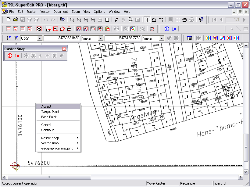
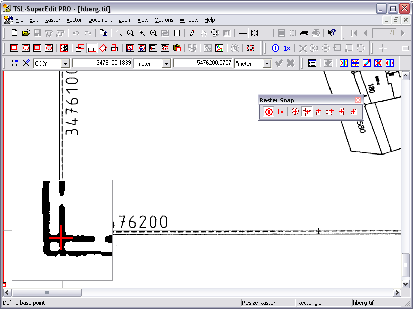
Open hberg.tif file and Zoom window around its left lower corner, so that the coordinates written there are legible, as shown below.
Click the Move raster button. Pick the left lower corner of the map as base point and type Tab 3476100 Tab 5476200 Enter to provide coordinates of target point. Again, this is just a preliminary move which precision does not have any influence on the calibration results, so no snapping or Magnifying Glass is needed. Choose the OTM - Accept option to complete the Move raster operation.
Click the Zoom extents button to show the entire map again, and the Calibrate raster button to show the Calibration toolbar.
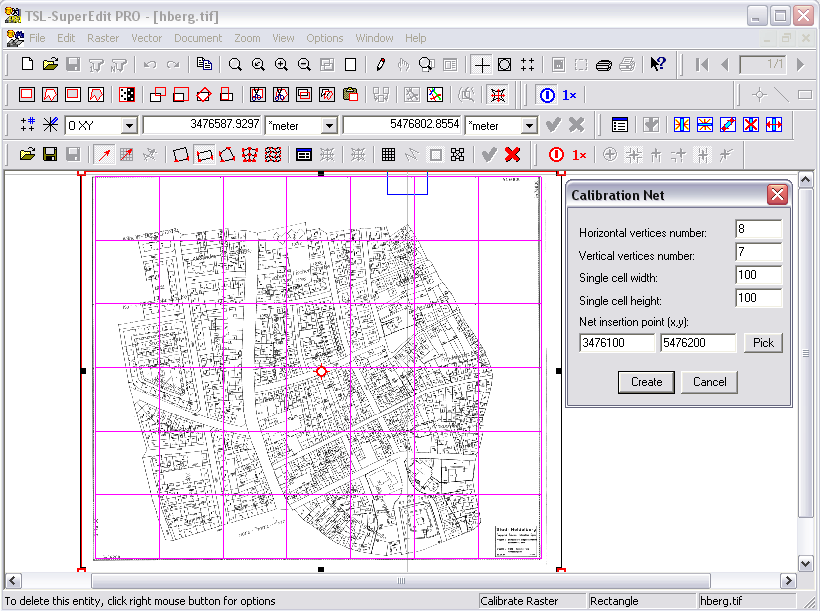
Push the Define net button on Calibration toolbar and type in the Calibration Net dialog parameters describing a reference network corresponding to coordinate marks printed on the map as small crosses:
Horizontal vertices number: 8
Vertical vertices number: 7
Single cell width: 100
Single cell height: 100
Net insertion point (x,y): 3476100,5476200
Push the Create button and check if the created net looks as on the picture above. In this zoomed-out view, it goes practically right through the marks.
Push the Add net-based vectors button on Calibration toolbar. The CALIBRATOR zooms automatically around the first corner of the defined net with the calibration vector attached to it; i.e. having the target location already defined.
Since the coordinate marks on the map have the regular form of small raster crosses, we are going to use raster snap to intersection. Choose the Options – Configuration option and check the Snap to raster active and Intersection of raster lines on the Snap tab. On the Magnifying Glass tab check the Magnifying Glass active, Verify every snap trial and Keep on display options.
For each target define corresponding Raster point by clicking the snap cursor at the corresponding coordinate mark and accept it with a right click. You may use Set options button on Calibration toolbar to change the AutoZoom level, if necessary.
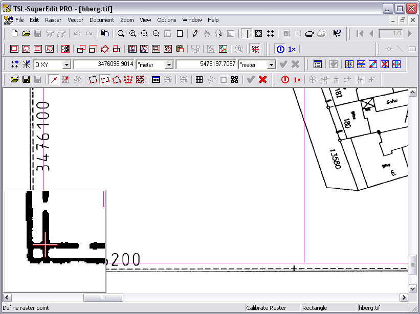
Magnifying Glass pops up for every snapped coordinate mark (intersection) and provides instant visual verification. Do not correct errors smaller than half a pixel - it does not have any statistical meaning and often is very subjective. Correct only those points that are obviously wrong, usually due to interference of some other lines with the cross mark, as shown below. You should need to correct no more than 5-6 snaps. Only at one point Raster snap will not find the intersection at all, so you must pick the correct point manually.
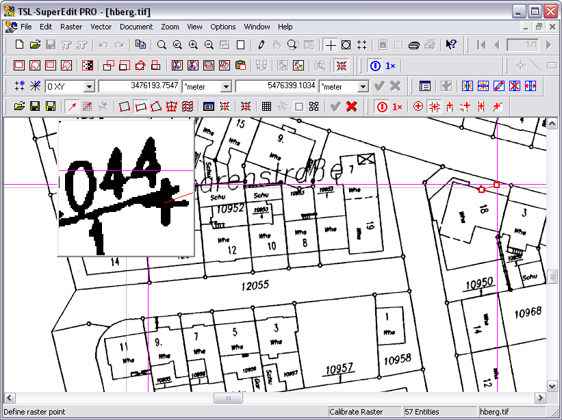
Simply pick a new position for the snap cross in the Magnifying Glass window and accept with usual right click.
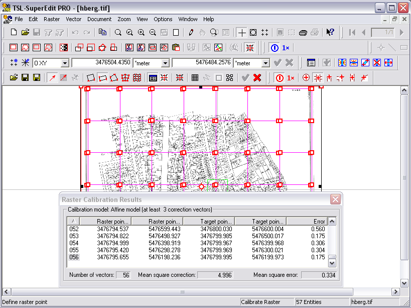
After defining Raster points corresponding to all 56 Target points of the net, push the Toggle vector list button to show the Raster Calibration Results dialog presenting complete, sortable numerical information concerning this calibration operation. Choose the Bicubic model using buttons on Calibration toolbar and check that Sqrt of mean square error that will remain after calibration is in the range of 0.219m (in world coordinates).
You may push the Toggle preview button and scroll through the list of Raster and Target points in order to evaluate visually differences between requested Target points and Calculated points depending on the Calibration model you choose. If you need to change something, you may delete points from the list or drag the red grip on the beginning of given calibration vector and correct it if necessary.
When using Calibration models higher than Bilinear, you must look at the calibration preview before executing it. Insufficient or badly selects calibration data, e.g. colinearly placed Target points, may result in perfectly small residual error and very bad deformation of the raster image between calibration points. Push the Zoom extents button and switch on the Toggle preview button. Calculated net should show only small and smooth deviations from the Reference net, as shown below. To check or change calibration nets colors push the Set options button on the Calibration toolbar.
When you are satisfied with the calibration preview, click the Execute button (or choose the OTM Execute option) in order to have the transformation applied to the image data. You may save the calibration report if you wish. After the calibration is executed, you may still keep the Raster Calibration Parameters dialog on the screen in order to examine the results by scrolling through the list of calibration vectors. If you want to get closer to some point, click at the Zoom in button on Main toolbar. Then use Undo and Redo buttons on Main toolbar to see that point before and after calibration. If you keep your Toggle preview button pushed, you should see that the Raster point is being moved by calibration to the end of the Calculated vector. To check or change calibration vector colors, push the Set options button on the Calibration toolbar.
Finish the calibration process by clicking the Accept button on the Calibration toolbar or choose the OTM Accept option. Optionally you may save the calibration vectors on file but, if you plan re-using them, remember to save the raster file just before doing the calibration, so that you may repeat the process using the saved vectors.
You may still Undo and Redo calibration changes from the Main toolbar. If you want to be able to repeat this exercise without reinstalling demo files, exit SuperEdit without saving the modified raster file, or choose the File - Save As.. option and give it a new name.
Zoom window around the left lower corner of the map, as at the beginning of this section. Snap to raster mark (intersection) at the left lower corner, as shown below.
All coordinate marks on the whole area of the calibrated map will show correct coordinates with accuracy better than 0.2 m in world coordinates. At 1:1000 scale, it means that the calibrated image accuracy is better than 0.2 mm across the entire map.
SuperEdit Cut / Copy / Paste editing is most often used for moving around selected raster areas within the same image or for transporting them between different raster images. SuperEdit operates in world coordinates, defines the insertion base point, and allows for rescaling and rotation while inserting raster blocks.
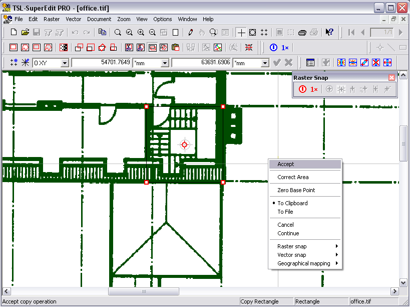
Open office.tif. Suppose that we need to create an insert showing the stairway scaled up two times. Click the Copy rectangle button on Raster toolbar. Select the OTM option: To File or To Clipboard. The latter does not require saving the file, just stores it as temporary object in clipboard. In case of the first option, do as follows: choose Pick corners of a rectangle to copy, starting from lower left corner. Choose OTM Accept option to accept default position of the insertion base point, shown as small gray circle. Then choose a name for copied raster image, e.g. stairway.tif.
Click the Paste raster button on Raster toolbar, select consequently OTM From File option. Choose the file name you have used in the Copy raster operation. Click Zoom extents button and place Target point in the empty area on the right side of the drawing. Now we are resizing the image being inserted; to do it numerically, type Tab 2 Tab 2 Enter, to put proper values into the Input bar boxes that display the X and Y scale. Since we do not want to perform the last rotating phase, choose the OTM Accept option to finish the whole action. SuperEdit inserts a scaled up image that you have copied to the stairway.tif - it should look similar to the figure below. With the To Clipboard option selected, always last copied image will be used.
Try other options of cut, copy and paste commands, e.g. using polygonal areas and various combinations of moving, resizing and rotating actions.
Scanned drawings often contain areas that require some cleaning in order to remove unwanted spots. Cleaning of empty parts of the drawing, like margins and bigger white areas, is best done using the Crop or Clear functions. Removing spots between drawing lines, however, may be done easier through filtering.
Start SuperEdit and open townmap.tcd. Double-click the townmap1.tif and townmap2.tif nodes on TCD Contents window to select them. You should see on the Drawing window that there is some dirt in the upper part of both selected subdocuments. It shows as a number of spots, as in the figure below.
Click the Filter spots / holes button on Raster toolbar. Choose a spot sample on the screen to define maximal spot size to remove; draw a rectangle over the area containing such spot. The OTM options appear automatically and you can read the calculated spot size, e.g. 29 for the lower spot and 40 for the upper one.
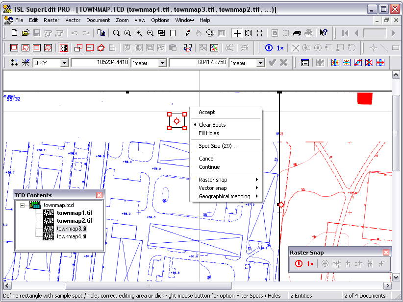
You can examine various spots on the drawing in this way or choose the OTM Spot size... option to enter your own value, e.g. 33. Finally, choose the OTM Accept option to start filtering. All isolated spots that are less than or equal to 33 connected pixels disappear from both selected subdocuments. You can compare the view before and after filtering by clicking the Undo and Redo buttons on Main toolbar a number of times.

Once determined, the value of spot size will be used as the default one in further executions of the Filter function, so you do not have to define it each time. Simply right-click to call the OTM options and choose Accept if the spot size is satisfactory.
The Filter spots / holes function must be used carefully as to not damage finer details of the image, like small texts or pattern lines. You can correct the editing area to some smaller one (e.g. covering only the place with dense spots). After starting the Filter spots / holes function, the rectangle defining editing area covers the common extents of raster drawings selected; you can correct it simply dragging its corners. Spots that are too large to be filtered out must be removed manually using the Clear rectangle or Clear polygon commands.
Instead of clearing spots, you may also fill small white holes that can appear on black parts of the drawing. The OTM Clear spots / Fill holes options let you choose the kind of filtering. Color or gray-scaled raster drawings cannot be filtered.
Exit SuperEdit without saving the filtering changes made to townmap.tcd subdocuments.
You may use Print command to print hybrid raster-vector documents. SuperEdit will be using your Windows printer. You may use the Control Panel – Printers to define the Default Printer and make sure that it is configured properly.
Open townmap.tcd composite background document (using SuperEdit’s Open) and add parcels.tvd vector drawing. Alternatively, you may open only estate.tcd that contains references to both foreground drawing and background images, if you created one before.
Use Zoom Extents button to display the whole drawing or perform Zoom Window to any part of it that you want to print. Click the Print Preview button on the Main toolbar or choose the File - Print preview option. Choose the DWM Landscape option. You should see the picture as this below:

During Print Preview action, you are actually working with a special vector drawing that is referred to as printing template. It shows you the white paper area on the gray background, with light-gray margins. A special rectangle drawn in blue determines the so-called print window – an area on the paper where the document (or its part) is to be printed. By changing the print window rectangle you are defining the shape of the paper-space viewport to the real world contained in the document. Left click inside the print window area to select it for dragging. Now you may drag its red grips placed at its corners to correct its shape or use the DWM Transform – Move / Scale options to redefine the viewport size and position.
You can place any vector entities, like lines, rectangles, texts and other objects to define drawing’s description and title, form additional borders, or create drawing head. Printing templates – with separate contents for portrait and landscape orientation – may be created independently using the Template Editor utility; you may connect desired template to the SuperEdit session using the Print tab on SuperEdit Configuration dialog.
To define the viewport characteristics determining projection from document to paper space, click the Print Window button on the Main toolbar. Now you are moved back to the document space, with its part covered by shape of the print window. You can drag the whole window to correct its position over the document, or drag its corners to changing its size relative to the document, actually redefining the scale the document would be printed. Alternatively, use appropriate OTM options to redefine the scale numerically; you can observe that the relative size of the print window accommodates the changes of scale. Finally, choose the OTM Accept option to resume the Print Preview function with print window characteristics redefined.

If you need to use a specific printer that is not currently selected as the Windows default, click the OTM Print Setup option.
Press the OK button to accept the print configuration, and click Print buttonon Main toolbar to start printing.
