
In the most typical situation SuperEdit window consists of menu, input and status bars, raster, vector and calibration toolbars (the last one only if the calibration command is invoked) and TCD Contents and Drawing windows.
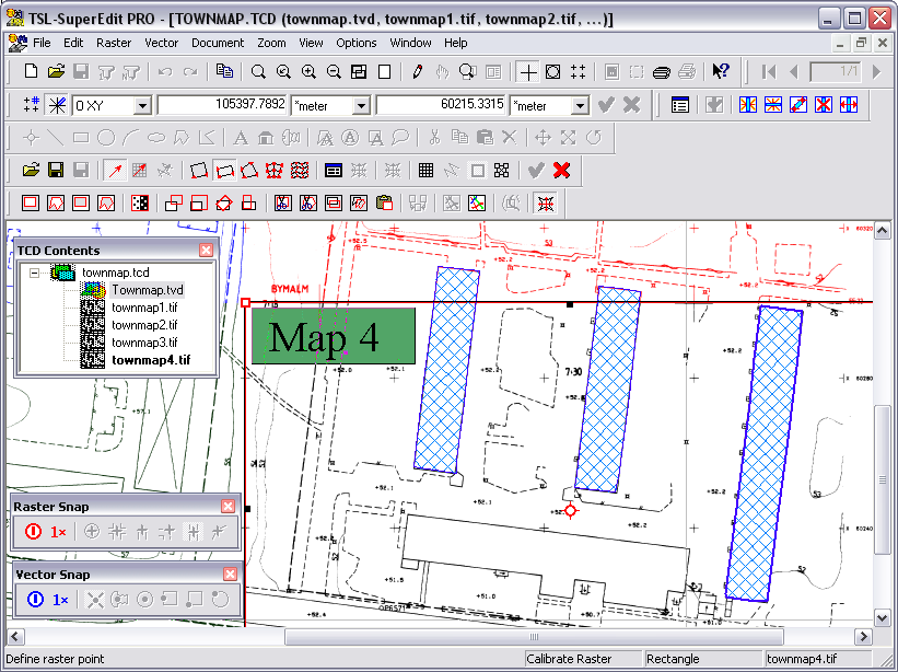
SuperEdit’s main window title bar shows application name and the name of the file with the opened single or composite document. In case of composite document, after its name there is a list of the first three component drawings shown in brackets. Below there is the main menu bar with pull-down command menus. A Main toolbar is displayed under the main menu bar. It contains buttons that allow access to the most frequently used commands. A Vector and Raster toolbars are displayed under the Main toolbar. They consist of buttons that allow access to vector and raster commands. An additional Raster Snap toolbar gives you instantaneous access to various raster snap modes. Similarly, an additional Vector Snap toolbar gives you instantaneous access to various vector snap modes. An optional Calibration toolbar with buttons specific to calibration command can be displayed below. An Input bar that is used to report cursor coordinates and to enter data from keyboard is displayed directly over TCD Contents and Drawing windows. Documents are displayed in the remaining place of the main window. A Status bar, also optional, is displayed under those windows. It shows the information that supports the user, such as message prompts, names of operations being performed and system Help information. All the bars are implemented in dockable fashion so do not treat the described layout as the unique one and arrange it according to your needs.
SuperEdit saves and restores its toolbars positions independently for maximized and restored positions of its window. This makes possible preparing two different layouts of toolbars suitable for large (maximized) and small (restored) windows, so that all necessary toolbars are always accessible. SuperEdit changes the layouts automatically as you switch from one window size to another.
The TCD Contents window is used to display a tree of inner structure of TCD image file. It is displayed if the TCD Contents option of the View menu is checked.
You can expand or shrink the structure by left mouse click in the little rectangle mark that is placed on the left from the TCD symbol and the name of TCD file. The structure can consist of raster and vector files. Both types are assigned different symbols so you can easily differentiate one from the other. It may happen that a TCD file has a link to a subdocument image file that is not available for the moment (e.g. it has been renamed or deleted). If you open such a TCD file, notice the symbol of red-crossed diskette that is assigned to the unavailable subdocument.
The red key is displayed on the symbol of subdocument that is opened in the read-only mode. The blue pencil is displayed on the symbol of vector TVD drawing that is selected for editing (marked as foreground). You may choose a vector drawing for editing by selecting exactly one of them. The open hand icon is displayed on the symbol of subdocument that is set disabled (i.e. is set invisible).
Double click on the symbol or the name of a subdocument selects this subdocument. The same result you can achieve by clicking the Select button on Composite Document dialog with this subdocument selected on Subdocument List. The thin, black frame with little, black squares on corners and in the middle of edges is drawn around extents of the selected subdocument. Repeated double left click cancels the selection. You can select more then one subdocument.
After right mouse click in a name or symbol of TCD or subdocument image file, a pop-up menu is displayed. It is described in User Interface paragraph.
If you open a single raster or vector file, then the TCD Contents window is not displayed even if the TCD Contents option of View menu is checked. However, you can still make SuperEdit embed this single image into a new TCD structure by using the Document - Switch to TCD Mode option. It makes the TCD Contents window visible, displaying the newly created structure. Use the Document - Switch to Image Mode to strip the TCD structure from the single image and turn the TCD Contents window off.
The Drawing window is used to display raster and vector drawings that are opened by SuperEdit directly or as subdocuments of a TCD document. Individual images, subdocuments in the composite document, can be selected for changing their attributes, their position in the common world coordinates and their visible areas (viewports). One subdocument, a vector TVD drawing marked as a foreground drawing, is automatically selected for editing when SuperEdit opens a composite document that references it. You can graphically select entities of TVD foreground drawing for various editing actions. Raster editing actions are visualized by graphical interfaces that utilize vector entities.
For each subdocument, its visible area, called viewport, is defined. Initially (after adding a drawing to the composite document) it is set to full drawing extents. A viewport becomes visible as a thin black frame if the corresponding subdocument is selected in TCD Contents window. To enable editing viewports use Document – Select / Edit Viewport option or click the Select button on the Main toolbar. They change the state of Drawing window from normal to selecting and vice versa. A viewport can be resized by dragging small black rectangles, called trackers. They appear in the corners and in the middles of edges of the selected drawing’s viewport. The Reset Viewport command resets the viewports of currently selected documents to their initial sizes (full extents of each respective drawing). See Select / Edit Viewports paragraph for detailed description of states and actions.
You can save and display named views that you are working with. See Views Manager paragraph for details.
Initially several toolbars are placed on top of the SuperEdit window. The main one with general viewing and printing functions and buttons for controlling SuperEdit documents named Main toolbar. The second one with dedicated functions for accessing raster drawings named Raster toolbar with Raster Snap toolbar placed along it. The next one with dedicated functions for accessing vector drawings named Vector toolbar with Vector Snap toolbar placed along it. Optionally other toolbars may be displayed during specific most complicated operations that require additional support, like the Calibration toolbar, which is shown only when the Calibration function is active.
You may show short description of each button by placing the mouse cursor over it. You may activate the toolbar buttons using the left mouse button click. Activating some buttons causes the SuperEdit Window to enter some special states that are indicated by showing those buttons pressed while the action is in progress. You may cancel the started action by depressing the activated button.
In the next paragraphs, all toolbars and buttons are described. Functions that SuperEdit performs as a result of clicking toolbars’ buttons are further described in appropriate paragraphs of SuperEdit Commands section. These paragraphs are referenced nearby description of each button.

Main toolbar contains several groups of buttons as follows:
File buttons - for controlling the New, Open and Save functions for document files (see File Commands paragraph);
Undo / Redo buttons- for going back and forth through subsequent steps of the editing process of opened document files (see Edit Commands paragraph);
Clipboard button - for controlling standard Copy Image clipboard functions (see Edit Commands paragraph);
Zoom buttons - for controlling the viewing scale and position of documents displayed in the SuperEdit Drawing window (see Zoom Commands paragraph);
Function buttons– for regenerating contents of drawing window (see Regenerate paragraph), defining and selecting viewports window (see Select / Edit Viewports paragraph), invoking the views manager window (see Views Manager paragraph), and call up Composite Document dialog window (see Image Properties paragraph);
Settings buttons – for direct access to several most popular settings from View tab of SuperEdit’s configuration dialog such as: crosshair, world-size cursor and grid. All buttons works as toggles;
Print buttons - for controlling the page layout, printed area, printer setup and executing print (see File Commands paragraph);
Help buttons - for accessing help (see Help Commands paragraph).

Vector toolbar contains several groups of buttons as follows:
Entity buttons - for creating basic geometrical elements in the current vector drawing (see Draw paragraph);
Spot buttons - for creating special complex labeled elements mostly for redlining (see Draw paragraph);
Editing buttons - for performing Cut / Copy / Paste selected entities to/from Windows clipboard and for deleting this entities from the current vector drawing (see Edit paragraph);
Transform buttons - for performing Move / Scale / Rotate operations on selected geometrical entities in the current vector drawing (see Transform paragraph).

Raster toolbar contains several groups of buttons as follows:
Clear / Crop buttons - for clearing rectangular or polygonal shapes in selected raster drawing(s) and cropping selected raster drawing(s) to rectangular or polygonal shape (see Raster Editing Commands paragraph);
Filter button - for removing spots or holes in selected raster files (see Filter spots / holes paragraph);
Transform buttons - for move, resize, rotate and change orientation operations on selected raster drawing(s) (see Raster Editing Commands paragraph);
Edit buttons– for cut, copy and paste rectangular or polygonal shapes from/to selected raster drawing (see Raster Editing Commands paragraph);
Merge button - for merging raster files (see Raster Editing Commands paragraph);
Create button - for create a new raster drawing (see Create raster paragraph) and for insert (rasterize) vector entities to raster drawing (see Insert vectors paragraph);
Trace button - for tracing raster drawing (see Trace raster paragraph);
Calibrate button - for performing calibration process (see Calibrate Raster Command paragraph).

Raster Snap toolbar contains buttons that are used to set and reset various kinds of raster snap.
First two buttons controls the snap mode in general:
Toggle snap button - for enabling or disabling permanent raster snaps, if the second Toggle single snap button is released, or for clearing or resetting single-click raster snaps, if the second Toggle single snap button is pressed;
Toggle single snap button - for controlling permanent raster snaps (using buttons from the next section) when released, or single-click raster snaps when pressed.
The next section of buttons are listed in a snap hierarchy order:
Snap to center of circular raster shape;
Snap to intersection of raster lines;
Snap to raster line end;
Snap to raster line corner;
Snap to center of raster line;
Snap to edge of raster area;
You can set more than one type of snap. If, for example, both raster line corner and intersection are detected within the snap pickbox area, the point of intersection that is higher in the hierarchy will be returned.
If you check some snap options SuperEdit activates a red pickbox to show the area where to look for a snap point. Depending on raster image contents and zoom level, you should chose a convenient pickbox size on the Raster Snap tab of Configuration dialog. After successful snap, the snap point is shown temporarily as small red cross.
You can use Raster Snap tab on Configuration dialog (see Configuration command on Options menu) as the other way to choose and set preferred permanent raster snaps. The state of Raster Snap tab settings correspond to Raster Snap toolbar buttons when the Toggle Single Snap button is released. Permanent raster snap options are stored in supered.ini file.
Snap modes that you choose using the OTM Raster Snap submenu options set the modes for single-click snaps. They correspond to Raster Snap toolbar buttons when the Toggle Single Snap button is pressed.

Vector Snap toolbar contains buttons that are used to set and reset various kinds of vector snap.
First two buttons controls the snap mode in general:
Toggle snap button - for enabling or disabling permanent vector snaps, if the second Toggle single snap button is released, or for clearing or resetting single-click vector snaps, if the second Toggle single snap button is pressed;
Toggle single snap button - for controlling permanent vector snaps (using buttons from the next section) when released, or single-click vector snaps when pressed.
The next section of buttons are listed in a snap hierarchy order:
Snap to crossing point;
Snap to insertion point;
Snap to center point;
Snap to mid point;
Snap to end point;
Snap to nearest point;
You can set more than one type of snap. If, for example, both crossing point and end point are detected within the snap pickbox area, the crossing point that is higher in the hierarchy will be returned.
If you check some snap options SuperEdit activates a blue pickbox to show the area where to look for a snap point. Depending on vector image contents and zoom level, you should chose a convenient pickbox size on the Vector Snap tab of Configuration dialog. After successful snap, the snap point is shown temporarily as small blue circle.
You can use Vector Snap tab on Configuration dialog(see Configuration command on Options menu) as the other way to choose and set preferred permanent vector snaps. The state of Vector Snap tab settings correspond to Vector Snap toolbar buttons when the Toggle Single Snap button is released. Permanent vector snap options are stored in supered.ini file.
Snap modes that you choose using the OTM Vector Snap submenu options set the modes for single-click snaps. They correspond to Vector Snap toolbar buttons when the Toggle Single Snap button is pressed.

Calibration toolbar contains several groups of buttons as follows:
File buttons - for loading correction vectors (from CAV file), saving them in CAV file and for saving calibration report in REP file;
Add buttons - for adding new correction vectors: free ones or based on net nodes or vector entities;
Model buttons - for selecting desired calibration model;
Results buttons - the first button for inspecting list of correction vectors with numerical details; the second for previewing graphical results of calibration;
Execute button - for executing calibration process;
Settings buttons – for defining calibration net or reference entities, choosing calibration frame and selecting calibration options;
Finishing buttons – for finishing calibration with accepting or canceling it.
All calibration commands are described in paragraphs of Calibrate Raster section.

New Raster Pages Toolbar allows you to scroll between pages in multiple- page raster drawings with single button click. You may also jump to specified page writing its number into edit box and pressing Enter. Additional Print All Pages button causes printing all pages at once. Raster Pages toolbar's buttons are accessible only with single, multi-page raster selected.

Edit Spaces toolbar contains three groups of buttons as follows:
Walls and Spaces Options button – single button group, use it to display Walls and Spaces Options dialog that controls various general geometrical parameters.
Validate Spaces button - single button group, use it to display Validate Spaces dialog that automatically starts a walls and spaces validating procedure. You can inspect any problem that the validating procedure detects and solve it by manual drawing edition or simply ignore it. Some classes of problems can be solved automatically (the feature is controlled by appropriate settings in INI file) and in this case they are reported as already solved (see Validate Spaces Command paragraph);
Editing Walls buttons - for adding, deleting and moving various kind of walls (see Add Vertical Wall, Add Horizontal Wall, Add Oblique Wall, Delete Wall and Move Wall paragraphs);
You can define and perform geometrically oriented actions - most common ones in the SuperEdit Drawing window- through the standard mouse interface consistent with the contemporary Windows application style. Use the left mouse button for pointing, clicking and dragging in various contexts. Use the right button click to display a pop-up menu with context-dependent contents.
In the normal state of the SuperEdit Drawing window,use the left click for selecting vector entities in the current vector drawing. The current entity is presented in selected state; small square-shaped red grips are displayed in some control points of the entity. To select a linear entity, like segment or polyline, click near to it. To select a closed entity, like circle, polygon or rectangle, click near to its edge or inside its area. To select a bitmap entity, like text or icon, click near to it or into the area covered by it. Press and hold down the Ctrl key to include new entities into selection or to exclude those already selected. Click an empty drawing area to remove the selected state from all entities.
If you move the cursor inside the red grip of some entity, it changes its shape from a cross to an arrow. It means that you may press the left mouse button and drag the cursor while holding the left button down, thus dragging appropriate control point of the entity. The original shape of the entity is drawn using light gray line; the dragged shape of the entity is drawn using thin black line, so you can observe your changes while dragging. Move cursor to desired position and release the left button to redisplay the entity in a new shape.
If you move the cursor over the edge of a polyline or a polygon, it changes its shape from a cross to a star. It means that you may press the left mouse button and drag the cursor while holding the left button down, thus adding new vertex to the pointed edge. The original shape of the entity is drawn using light gray line; the dragged shape of the entity is drawn using thin black line, so you can observe your changes while dragging. Move cursor to desired position of new vertex and release the left button to redisplay the entity in a new shape.
In both situations described above, you may click the right mouse button to display pop-up menu with Drag, Add Vertex and Delete Vertex options available. The set of options displayed depends on the place you clicked. Choose the Drag or Add Vertex option if you want to perform appropriate dragging actions as described above, but without holding the left mouse button down. It gives you access to scrolling or zooming actions while dragging, entering values from Input bar, or possibility right-clicking once again to use pop-up Options and Tools Menu (OTM), e.g. to set single-click snap. Choose the Delete Vertex option when adequate, if you want to delete the pointed vertex from a polygon or a polyline.
During most dragging actions, when you define vector entities, you may press the F8 key to force the ortho mode relative to the starting position or to the recently entered point. Current cursor position is translated so that the dragging is performed only horizontally, only vertically, or along the 45° line, depending on which distance from the actual cursor position to the horizontal, vertical or diagonal line is the smallest one.
All simple vector entities (excerpt polylines, polygons and complexes) have center grips (small circle with axis lines) that can be used to move the whole entity using drag&drop method.
If you click the right mouse button while the cursor is displayed as a normal cross, the standard pop-up Drawing Window Menu (DWM) is displayed, with options described in following sections.
You may use the shortcut for entering the Zoom Window action by pressing the left mouse button and dragging the cursor while holding the left button down. This shortcut is accessible only in the normal state of Drawing Window.
You may use the shortcut for entering the Select Window / Crossing action by pressing the Ctrl key on the keyboard and then pressing the left mouse button and dragging the cursor while holding the left button down. You can observe changes of the cursor shape and hints in status line displayed appropriately. This shortcut is accessible only in the normal state of SuperEdit Drawing window.
If you want to inspect some area of the SuperEdit Drawing window, move the mouse cursor to that area and press the Ctrl+Q key. The Magnifying Glass window pops up, showing the area of interest in greater detail.
Specific mouse actions that depend on current activities performed by SuperEdit, e.g. during selecting subdocuments or defining print window will be described separately.
Specific actions can be accessed through pop-up menu that is displayed after clicking the right mouse button. Some actions are common to various contexts, while the other ones are specific to certain states of the SuperEdit Drawing window. They will be described in the sequel. Generally, a list of pop-up menu items depends on a window that is clicked, the place the click is made, and the state of the action being performed.

Options and Tools pop-up menus (OTM) are available during performing various commands (concerned with raster editing, vector editing or some other action, e.g. defining print window). OTM’s content is command-dependent but some options are common to almost all commands. Those are raster snap options, geographical mapping options, auto zooming options and Cancel and Continue options.
The OTM Cancel option breaks and discards the command that is being defined. The OTM Continue option switches off the OTM so you can go on with the command.
The OTM that is displayed while you are in the middle of some complex operations can contain OTM Default, OTM Accept or OTM Reject option. Use the OTM Default option to choose the default value of the parameter just being defined. In most cases this default is shown graphically and a Status bar hint clearly defines what kind of parameter we are talking about. Use the OTM Accept option to accept all data entered so far and execute the command or go to its next stage. The OTM Reject option lets you withdraw just started dragging. Use it instead of the OTM Cancel option or instead of pressing the Esc key if you want to clear only the data just being entered, instead of canceling the whole operation.
There are other command-dependent OTM options that let you go back to specified stage of command defining process and in this way redefine various command parameters. They are explained in paragraphs where those commands are described.
The raster snap options are described in details in Raster Snap tab and Raster Snap toolbar paragraphs. OTM presents the following snap modes on the Raster Snap sub-menu:
RS Circle - Snap to center of circular raster shape;
RS Intersection -Snap to line intersection;
RS End -Snap to line end;
RS Corner -Snap to line corner;
RS Center -Snap to centerline;
RS Edge -Snap to edge of raster area;
Raster snaps set by the OTM Raster Snap options are valid for a single click only. You can set and use them independently on those snaps that are defined as permanent ones by Raster Snap toolbar or with Raster Snap tab of Configuration dialog. If you check some snap options, SuperEdit activates a pickbox (as a red rectangle) to show the area where to look for a snap point. Depending on the raster image contents and the zoom level, you should chose a convenient pickbox size on the Raster Snap tab. The OTM Raster Snap sub-menu is checked when some raster snaps are active.
The vector snap options are described in details in Vector Snap tab and Vector Snap toolbar paragraphs.The options are enabled if there is a TVD vector drawing selected. OTM presents the following snap modes on the Vector Snap sub-menu:
VS Cross - Snap to crossing point of vector entities;
VS Ins - Snap to insertion point of vector entity;
VS Center - Snap to center point of vector entity ;
VS Mid - Snap to mid point of vector entity;
VS End - Snap to end point of vector entity;
VS Near - Snap to nearest point of vector entity.
Vector snaps set by the OTM Vector Snap options are valid for a single click only. You can set and use them independently on those snaps that are defined as permanent ones by Vector Snap toolbar or with Raster Snap tab of Configuration dialog. If you check some snap options, SuperEdit activates a pickbox (as a blue rectangle) to show the area where to look for a snap point. Depending on the vector image contents and the zoom level, you should chose a convenient pickbox size on the Vector Snap tab. The OTM Vector Snap sub-menu is checked when some vector snaps are active.
The same Geographical Mapping entry with its sub-menu is appended to the OTM and DWM pop-ups as well. The OTM Geographical Mapping sub-menu is checked when some geographical mapping is active. The sub-menu of the Geographical Mapping option consists of the items described below.
0 None - If the 0 None option is set, SuperEdit does not use geographical mapping at all. The check mark placed at the None option indicates that no mapping is active. The coordinate system and units used in this case are determined by settings of the coordinate system and presentation units combo boxes on the Input bar;
1, 2, 3, 4 Recent - Use Recent option to select one of the geographical mapping systems recently used. Names of these mappings are listed on subsequent items of sub-menu. The check mark placed at the mapping name indicates that this mapping is active. SuperEdit remembers up to four mappings. They are numbered from one up to four (zero is reserved to None mapping option item). The order of mapping system sequence on the sub-menu matches the selection history. The absence of Recent items suggests that geographical mapping has not been used in the configuration taken from the supered.ini file. The check mark placed at the mapping name indicates that this mapping is active. The names and the order of mappings are saved in the supered.ini configuration file and set automatically after starting the application again;
Select... - Use Select...option to set the current geographical mapping system. After entering the option, the Geographical Mapping dialog is displayed. It is described in details in Geographical Mapping paragraph. The chosen mapping becomes the current one. It means that all entered, displayed and edited coordinates are interpreted using the current mapping. Its name is displayed on sub-menu as Recent mapping item and checked.
The OTM for Calibrate Raster and Trace Raster command contains Auto zoom option with its sub-menu. You can use the option to define if and how deep zoom should be performed automatically around subsequent points involved in current action. The sub-menu of the OTM Auto zoom option consists of the following items:
None – use it to switch off the auto zoom feature;
Current – choose the option to use the zoom level established manually;
M:N group of options – by choosing any of these options you define the zoom level as M screen pixels to N raster image pixels (in case of several raster drawings involved, the smallest raster pixel is taken into account).
The current setting of the auto zoom feature is marked by the dot mark on the corresponding sub-menu item. The whole OTM Auto zoom sub-menu is checked when some auto zoom level is active.
Generally, the content of the Drawing window pop-up menu (DWM) depends on the state of selection in this window and state of Drawing window itself. The DWM is displayed only if exactly one vector drawing is selected for editing. The same Geographical Mapping entry with its sub-menu is appended to the OTM and DWM pop-ups as well. These items are described in OTM paragraph.
You may use the DWM options as well while in the Print Preview mode.

In the case of an empty selection (no entity is selected), a pop-up menu that is displayed after a right mouse button click consists of three options.
Repeat (Last action)- it let you start the last action that you have been done, e.g. Draw Polygon;
Paste – the option is enabled if a contents of clipboard is defined by the last successful Copy comand; use the option to paste the contents;
Drawing Properties – use the option to enter a tabbed dialog Drawing Properties where you can examine, define and edit units, tools, layers, text styles and patterns for the whole drawing (see Drawing Properties dialog for detailed description).
All options are also available as sub-options of Vector menu. You may find their detailed explanation in Vector Editing Commands paragraph.
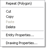
In the case of both single and multiple entity selection, the DWM consists of the same options.
Repeat (Last action)- it let you start the last action that you have been done, e.g. Calibrate Raster;
Cut - use the option to cut selected entities to the clipboard;
Copy - use the option to copy selected entities to the clipboard;
Paste - the option is enabled if a contents of clipboard is defined by the last successful Copy comand; use the option to paste the contents;
Delete - use the option to delete selected entities;
Entity Properties...;
Drawing Properties... .
Entity Properties... options enters the Entity Properties tabbed dialog where you can examine, define and edit parameters concerned with that entity. In the case of a single complex entity or multiple entity selection, the first tab named Components on the Entity Properties dialog lets you choose the appropriate entity from the list or from the preview window displayed within the tab. In the Tools and Style tabs on the Complex / Selection Properties dialog you can examine, define and edit parameters that become the common ones for all components of a single complex or for all selected entities in a multiple selection. Initially, only the tools and style parameters with the same values for all entities are shown. You can leaves some values empty, meaning different for different entities, or define values for those that should be equal for all entities in the current selection (see Drawing Properties dialog for detailed description).
Drawing Properties option enters a tabbed dialog Drawing Properties where you can examine, define and edit units, tools, layers, text styles and patterns for the whole drawing (see Drawing Properties dialog for detailed description).
All but first options are also available as options or sub-options of Edit option on Vector menu. You may find their detailed explanation in Edit paragraph.
The composite document pop-up menu (CDM) that are available in TCD Contents window after performing right-click into specific node displayed within tree structure, groups commands for composite document management on the document and subdocument level.
If a node that correspond to a TCD document is clicked by the right mouse button the CDM options are displayed as in the following picture.
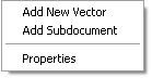
The first option is available as Add New Vector option and the second – as Add Subdocument option, both on Document menu. The Properties option launches Composite Document Parameters dialog. All options are described in appropriate subparagraphs of Document commands paragraph.
If a node that corresponds to a raster or vector subdocument is clicked by the right mouse button, the CDM options are displayed as in the following picture.

The options correspond to the buttons of the Composite Document dialog that is launched by Image properties command on Document menu or Image Properties button on Main toolbar.
If you click the CDM Disable option (it makes the drawing invisible) and then call the CDM options for the same node again, you can see that the CDM Disable option is replaced by the CDM Enable option. If you click the CDM Enable option that it makes the drawing visible, you get the CDM Disable option available again. Similarly, the CDM Select / Deselect options are mutually replaced. If you click a “vector” node, the Properties option launches Vector Drawing Properties dialog; click a “raster” node - launches Raster Drawing Properties dialog.
The CDM Reset Viewport option lets you reset the current viewport’s extents to their original, full size.
All options and dialogs are fully described in appropriate paragraphs of Raster, Vector and Document editing commands sections.
You can perform some more detailed actions using dialogs. Simple single-form dialogs, as well as multiple-form-tabbed dialogs, describe various contexts of the subject they serve.
The Properties dialogs are implemented as tabbed dialogs. Use the OK button to introduce all changes made in the dialog and to close it. Use the Cancel button to discard all changes made in the dialog and to close it. Use the Apply button to introduce all changes made in the dialog and to keep the dialog open. In the last case the OK button is replaced by the Close button (it can be used to close the dialog) and the Cancel and Apply buttons become disabled. Any subsequent change made in the dialog enables the Apply button again.

The Input bar displays current cursor coordinates and allows you to control the coordinate system and the units they are expressed. You may activate snap to grid in drawing operations, using Grid snap button placed on the left side of Input bar (you may hit F9 key instead). Similarly, you may activate orthogonal snap, using Ortho snap button placed next to Grid snap buttonon the Input bar (you may hit F8 key instead). Both F8 and F9 keys are used as toggles.
The coordinate system name is displayed within the combo box placed on the left side of the input bar. In normal state the absolute coordinate system, denoted as OXY, is the only one accessible for inspecting current cursor coordinates. During editing actions, you may change it to the relative coordinate system denoted as @XY, or the distance – angle system, denoted as D<A. The values of coordinates are computed relative to the point defined recently. In some actions, like rescaling or rotating, you have additional possibility to control defined values by scale system (denoted as SxSy) or relative angle system (denoted by @<A), forced accordingly in appropriate phase of transforming action. Each time you may switch to other coordinate system at your will.
With Geographical Mapping option set, coordinate system combo box on the Input bar is completed by the following systems:
OGM - absolute geographical coordinates (relative to the 0,0 point);
@GM - relative geographical coordinates (relative to the recent point - during editing).
You may display and enter geographical coordinates in degrees (in decimal or DMS format), grads or radians using the presentation units combo box on the Input bar.
The presentation units are displayed within the combo boxes placed after each coordinate. The distance units are initially defined by document units (see Document – Properties option). The document units are marked in the combo lists by an asterisk placed in front of units’ name. Change of presentation units does not change the document units; however, change of document units forces resetting presentation units to new value. The angle units – accessible when angular value is displayed in appropriate coordinate box – may be chosen between degrees in decimal or DMS format, grads or radians.
After activating the coordinate boxes, you may write down your own values. It has sense only during editing actions, of course. You may activate the desired coordinate box by pointing with cursor and clicking, or simply by hitting the Tab key while defining the new point to activate the first coordinate. Write down desired value and hit Tab again to move to the second coordinate. Click the Enter button or hit the Enter key on the keyboard to force written values as if you clicked left mouse button into Drawing window with desired coordinates. During writing new values, moving the mouse cursor over the Drawing window has no effect on displayed values, because you have stared entering your own ones. If you want to withdraw your changes, click the Skip button or hit the Esc key on the keyboard to resume the input back from the Drawing window. Cut, copy, paste and undo operations also apply for the entered values.
If you move cursor on the XCoord or YCoord box (watch change of cursor’s shape) and leave it there you can use keyboard and enter your own data. Accept it by Enter button. Treat Input bar as alternative to the mouse source of data. In some cases you can enter an angle in degree units (while rotation interface is active) or scales for x and for y-axes (while resize interface is active).

The left part of a Status bar displays explanations, hints, progress and status information concerned with the currently performed actions. The right part of the Status bar displays the name of current action and the name of single, selected subdocument. If the selection consists of several entities the number of these entities is displayed instead. If the number of selected subdocuments is greater than one, this number with number of all subdocuments contained in the TCD document is displayed.
