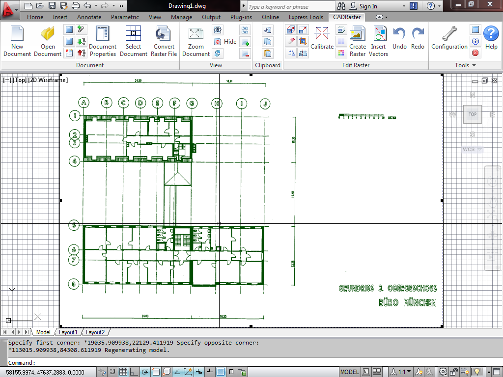
CADRaster provides tools for productive utilization of scanned drawings and other raster images in AutoCAD and its applications. It enables all versions of AutoCAD to display monochrome, gray-scale and color raster images. The scanned drawings and pictures are shown on the AutoCAD screen together with AutoCAD drawings (DWG) and processed using tools integrated with AutoCAD commands. Raster and vector data coexist in the AutoCAD session and are well defined in the same coordinate system, so that operations like zooming, panning and matching of raster images and vector drawings may be done easily and precisely.

CADRaster 15 is distributed in two versions, LTX and PRO, that both run on the same AutoCAD platforms: 2012, 2013, 2014 and 2015. CADRaster LTX offers a simpler selection of raster editing tools and it is limited to editing B&W images only. CADRaster PRO adds important functions, like image calibration, cut/copy/paste editing or raster lines tracing. It also edits color raster images.
Important
Due to AutoDesk licensing policy, CADRaster is no longer available for AutoCAD LT 2015.
This manual describes all features and commands available in both CADRaster versions. Commands that are available only in CADRaster PRO are marked as (PRO only) accordingly.
Both CADRaster versions use the same data formats and code, so projects in progress may be easily moved between different AutoCAD and CADRaster versions without any compatibility problems.
CADRaster is based on Tessel Systems composite document viewer. It allows combining of an arbitrary number of raster documents, and, optionally, even vector drawings, into one composite document. Individual images, sub documents in the composite document, can be selected for changing their attributes, their position in the common world coordinates and their visible areas (viewports). One sub document, a vector drawing marked as a foreground drawing, is automatically opened by AutoCAD when CADRaster opens a composite document that references it.
CADRaster offers powerful set of commands to edit raster images so you can:
crop raster image and change its dimensions,
clear rectangular and polygonal areas of raster image,
calibrate raster image using known coordinates or vector references (PRO only),
rotate or align raster image around any angle,
rotate image by 90 degrees,
resize raster image or match it with vector data,
filter spots or holes to clean raster image,
change density of raster image,
cut or copy rectangular or polygonal areas of raster image,
paste raster image from clipboard or file (PRO only),
merge several raster images,
insert vector entities into raster image (PRO only),
create raster images from vector drawings,
define transparent areas in color raster image (PRO only),
split raster image into several smaller images and automatically add them to the composite document (PRO only).
Composite documents are stored in files with the TCD (Tessel Composite Document) extension and can also be embedded in other documents. In the current implementation composite documents contain references to documents that are stored in separate files. Composite documents are especially useful in GIS applications for seamless display of neighboring or overlapping sections of raster and vector maps.
They are also useful in engineering applications, whenever multiple scanned images need to be integrated into a single larger document, different drawing versions compared, or raster images presented together with vector drawings in a controlled way. CADRaster supports Single Image Mode that facilitates viewing and editing of single raster files without creating trivial composite documents that refer to one image file only.
CADRaster displays composite documents that refer to sub document files saved in various raster and vector formats. The full list of formats supported by CADRaster can be found in the section called “Appendices”. File names of raster and vector sub documents must have extensions appropriate for their formats. The terms: sub documents, drawings and images will be used in this manual as equivalent, whenever it is unambiguous.
CADRaster PRO offers an important feature that facilitates processing maps. The World Coordinates bar displays cursor position in geographical coordinates based on appropriate graphical mapping. Additionally you can enter coordinates of points expected by AutoCAD’s or CADRaster’s commands using geographical coordinates.
Scanned and vector documents displayed by CADRaster can be printed together with the current AutoCAD’s drawing using the standard PLOT command. You can print hybrid documents on any device, printer or plotter, which is controlled by an MS Windows graphics printer driver. CADRaster can print to standard MS Windows drivers, drivers provided by printer/plotter vendors or drivers developed by Tessel Systems for selected raster devices.
CADRaster can efficiently print documents of any size up to the maximum supported by the given output device. The printing process is always performed using the full resolution data from the scanned or vector document file scaled to the demanded output size.
CADRaster can print DWG solids and other vector entities either opaquely or transparently on the background of raster images (PRO only).


