
This chapter is a guided tour through the most common ways of using CADRaster.
In order to provide you with some drawings to play with, Setup has installed a number of sample documents in the DOC subdirectory.
But first let’s have a closer look at the two cornerstones of CADRaster: hybrid raster-vector editing and Tessel Composite Documents.
In contrast to large format raster editors that operate directly on a bitmap image of the scanned document, CADRaster uses a hybrid raster-vector technique that builds on the following:
full resolution scanned document is kept always as a file on the hard disk - its raster data is never loaded to RAM, so it does not compete for the computer resources;
AutoCAD shows views that are calculated by CADRaster on as needed basis according to the current zoom extents and resolution requirements;
nominal parameters like orientation, scale, units, insertion point, are used in order to present the views correctly mapped into AutoCAD’s world coordinate system;
the scanned document is shown as a raster background for the foreground DWG drawing on which AutoCAD and its applications can operate normally;
both the raster background and the foreground DWG are always registered properly in the same world coordinate system and can be zoomed and panned simultaneously using the standard AutoCAD commands;
CADRaster provides tools for controlling and editing of the background raster images, primarily by defining the coordinate system for them and providing tools for clearing selected areas of raster, cut/copy/paste editing, and more advanced operations like multi-point calibration of raster images;
AutoCAD provides tools for drafting that may be used to create new lines, symbols and texts that are kept in the DWG foreground drawing; both AutoCAD and CADRaster commands may use osnaps and selective raster snaps;
CADRaster may insert selected vector entities to raster backgrounds and rasterize whole vector drawings;
both background and foreground drawings can be printed together as one hybrid document using the standard AutoCAD
PLOTcommand.
In order to represent scanned data in the AutoCAD's world coordinates CADRaster uses a number of parameters that describe the scanned data and the original paper drawing. These parameters are:
raster size- scanned image size in pixels, also referred to as the width, and the number of lines;resolution- image resolution equal to the scanner's resolution, if not changed by later processing, in dots/inch;orientation- 90°, 180° or 270° rotation needed to position the scanned image properly on the screen;scale- the nominal scale of the original drawing needed to determine the represented world size;units- measuring units in which the world will be dimensioned;insertion point- used to place the image in the coordinate system, so that the origin is properly defined, expressed in units.
In order to describe how these parameters are applied, let's use a simple notation [a X b] to denote a rectangle of dimensions a and b.
Raster size, i.e. the physical dimensions of the scanned image in pixels and lines, is known from the image file itself.
Raster size and resolution are used to determine the original paper size in inches:
paper [width X length] = scan [pixels X lines] / resolution
Then, the orientation is used to position the image properly, so that it appears as we want it on the screen:
for 0° and 180° : image [width X height] = paper [width X length]
for 90° and 270° : image [width X height] = paper [length X width]
The image dimensions are then converted to the corresponding world dimensions using the scale and units parameters:
world [width X height] = image [width X height] * scale * (units/inch)
Finally, the origin of the coordinate system is established by defining the insertion point, i.e. the coordinates of the left lower corner of the image, as it appears after all the above transformations applied. This way, the above defined world width and height become the image's extents in the AutoCAD's world coordinates.
Important
Please note that this functionality is available only in CADRaster PRO
To facilitate working with geographical maps, CADRaster lets you use geographical coordinates and convert them to orthogonal coordinate system back and forth.
New submenu on the CADRaster OTM menu (activated by CTRL+RightClick hot key) labeled "Geographical mappings..." activates the CADRaster World Coordinates bar.
The World Coordinates bar displays current mouse position converted to selected geographical mapping system.
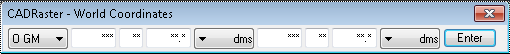
You can use the World Coordinates bar to enter points coordinates specified in geographical coordinates.
You can move keyboard input focus to the World Coordinates bar using CTRL+TAB key or clicking on the coordinate edit box and modify coordinate value manually.
After clicking the Enter button (or pressing the Enter key) the current coordinates are converted to the orthogonal coordinate system and sent to AutoCAD's command area.
Conversion routines are based on geographical mapping systems that are described later.
CADRaster is built using the newest generation of hybrid raster-vector editing tools called Tessel Composite Documents (TCD). TCD offers an important generalization of the hybrid editing concept: the background document may consist of any number of raster sub documents and optionally vector background documents, placed in the common world coordinate system and functioning as a single logical document.
CADRaster, as all TCD-compatible applications (like viewers, editors, integrator libraries), utilizes a common Composite Document Dialog that provides the necessary tools to operate on composite documents on both the main document and subdocument level.
In the AutoCAD environment you may simply look at TCD sub documents as additional layers that are controlled by CADRaster.
TCD raster sub documents have the following important features:
they may contain raster images in any format supported by Tessel Software Line including monochrome, grayscale and color raster images;
they may be properly mapped to the common world coordinate system using the resolution, orientation, scale, units and insertion point parameters;
monochrome raster images may have a logical color independently assigned;
raster images may be edited using CADRaster commands.
TCD vector sub documents have the following important features:
optionally supported background vector subdocuments may contain vector files in DWG and DXF format;
they may be properly mapped in the common world coordinate system using the units and orientation parameters independently set for each subdocument;
one of DWG vector sub documents can be marked as foreground drawing.
Foreground drawing is not displayed by CADRaster but by AutoCAD itself. When CADRaster opens a Tessel Composite Document that contains a reference to a foreground drawing, it calls AutoCAD to open that foreground drawing. This behavior can be controlled by the Open foreground drawing option in the CADRaster Configuration dialog. DWG drawing currently opened by AutoCAD can be inserted as a foreground drawing to the current TCD using the RDWG2TCD command.
Start CADRaster by double-clicking its icon that has been created by setup. This will start your AutoCAD in the usual way and, in addition to the standard AutoCAD menu and toolbar, you should see the CADRaster toolbar, as in the figure below.
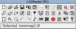
You can see the name of each toolbar button in a ToolTip. When you point to a button with the mouse cursor for a longer while, the button’s name will appear in a box. We will use those names while referring to the buttons later in this manual.
Depending on the status of CADRaster session some of the buttons may be inactive and displayed with grayed faces.
If the toolbar is not there, it is possible that somebody has turned it off. In such a case just type RMenu or the CADRaster command that should display it again.
If, as a response to the RMenu command, you get the Unknown command message from AutoCAD, it means that CADRaster is not installed or not configured properly.
Refer to chapters on the installation and configuration for more details.
Most of CADRaster commands may be flavored in various ways by choosing one or more options from their Options and Tools Menu (OTM).
When a command is called for the first time, its OTM pops up automatically, so that the user must choose the necessary options, e.g.
for the Cut command you must choose either Rectangle or Polygon and either Clipboard or File, as shown below:
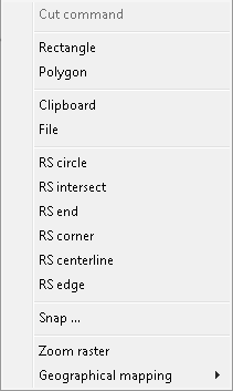
When the same CADRaster command is called next time, it assumes that the previously chosen options should be used, so that you don’t need to repeat the same clicking again.
When any change is needed, you may simply use the OTM hotkey (default: Ctrl+RightClick) immediately after clicking the command’s button on the toolbar and choose new options for the command.
Besides command options OTM provides convenient access to various tools,
like command parameters, transparent raster snaps (RS) and the Zoom raster command.
You can redefine OTM hotkey using RCfg command (see Other tab description).
CADRaster working on AutoCAD (from AutoCAD 2012) loads CADRaster ribbon into standard AutoCAD’s ribbon.

Important
If CADRaster’s ribbon is not present you may load it using AutoCAD’s _NETLOAD command.
To do so invoke _NETLOAD and select CADRaster Ribbon.dll file available in folder, where CADRaster was installed.
Warning
CADRaster ribbon can not be loaded to AutoCAD LT.
Whole CADRaster’s ribbon is divided into 5 sections:
Document
View
Clipboard
Edit Raster
Tools
This section contains commands to navigate on raster documents.
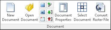
New Document (RNew command) - creates new, empty TCD document.
Open Document (ROpen command) - opens existing TCD or single raster document.
Save Document (RSave command) - saves currently opened document.
Save Document As... (RSaveas command) - saves currently opened document using different name.
Close Document (RClose command) - closes currently opened document.
Add DWG to TCD (RDWG2TCD command) - adds to TCD document reference to current DWG file.
Import image (RImport command) - imports images drom DWG.
Export image (RExport command) - exports images to DWG.
This section contains commands to manage views of raster documents.
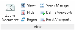
Zoom Document (RZoom command) - zoom whole raster or TCD document.
Show (ROn command) - shows document (if it was hide by ROff command).
Hide (ROff command) - hides document.
Regen (RRegen command) - regenerates raster document view.
Views Manager (RView command) - shows Views Manager window.
Define Viewports (RVports command) - defines viewports for raster images.
Reset Viewports (RResetvp command) - resets viewports defined using RVports command.
This section contains commands to manage clipboard operations.
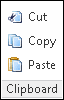
Cut (RCut command) - cuts selected area of raster image to clipboard or file.
Copy (RCopy command) - copies selected area of raster image to clipboard or file.
Paste (RPaste command) - paste from clipboard or file.
This section contains raster editing commands.
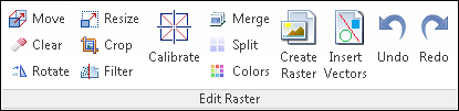
Move (RMove command) - moves raster image.
Clear (RClear command) - clears raster areas using rectangles or polygons. Also allows to define transparent areas.
Rotate (RRotate command) - rotates or align raster image.
Resize (RMatch command) - matches or resize raster image.
Crop (RPage command) - crops image or define page.
Filter (RFilter command) - filters spots, holes or change density.
Calibrate (RCalib command) - calibrates raster image.
Merge (RMerge command) - merges raster images.
Split (RSplit command) - splits raster image to TCD document.
Colors (RColors command) - defines fill, filter or transparent colors.
Create Raster (RCreate command) - creates raster image.
Insert Vectors (RInsert command) - inserts vectors to raster image.
Undo (RUndo command) - undo last CADRaster command.
Redo (RRedo command) - redo last CADRaster command.
This section contains utility commands.
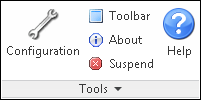
Configuration (RCfg command) - shows CADRaster configuration dialog box.
Toolbar (RMenu command) - shows or hide CADRaster toolbar.
About (RAbout command) - shows information about CADRaster.
Suspend (RSuspend command) - suspends current CADRaster editing command.
Help (RHelp command) - shows CADRaster help.
The most fundamental function of CADRaster is to enable viewing of full-size scanned drawings and composite documents inside AutoCAD. The viewing function has been implemented in such a way that zooming, panning and all other AutoCAD functions may be done using standard AutoCAD commands.
Click the Open button on the CADRaster ribbon. Choose File Type TIFF and open the file office.tif from the CADRaster’s DOC subdirectory.
The image should get opened and, as a result of default configuration options, it should be automatically zoomed to its full extents and selected for editing.
All buttons of the CADRaster ribbon, except of Undo and Redo, should be active, and its status line should read Selected: office.tif.
Move the AutoCAD cursor around to see that its coordinates would make sense for a building floor measured in millimeters.
This results from the values of parameters that have been set for the office.tif image.
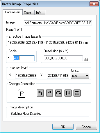
Press the Control doc button of the CADRaster toolbar.
Since the program runs in the Single Image Mode, this button will directly show parameters of the only raster image that is opened at the time, as in the figure below.
The Parameters page of the Raster Image Properties dialog shows the full path to the image file, Effective Image Extents in the current Units (mm), the nominal Scale (1:400) and Resolution (300x300) and the Insertion Point coordinates. All those parameters make it possible for CADRaster to place the image in the world coordinate system, so that it may be compatible with overlaid AutoCAD drawings. Close the Raster Image Properties dialog.
Use AutoCAD’s Zoom command to view different parts of the scanned drawing.
There is no DWG drawing opened at this time, so instead of Zoom/Extents use the Zoom Document button on the CADRaster ribbon.
Drafting on the background of scanned drawings may be the most natural application for CADRaster.
As the background documents can be properly mapped into the AutoCAD’s world coordinate system, it is possible to work using normal dimensions and standard symbol libraries.
While having the scanned drawing office.tif opened (see the previous section)
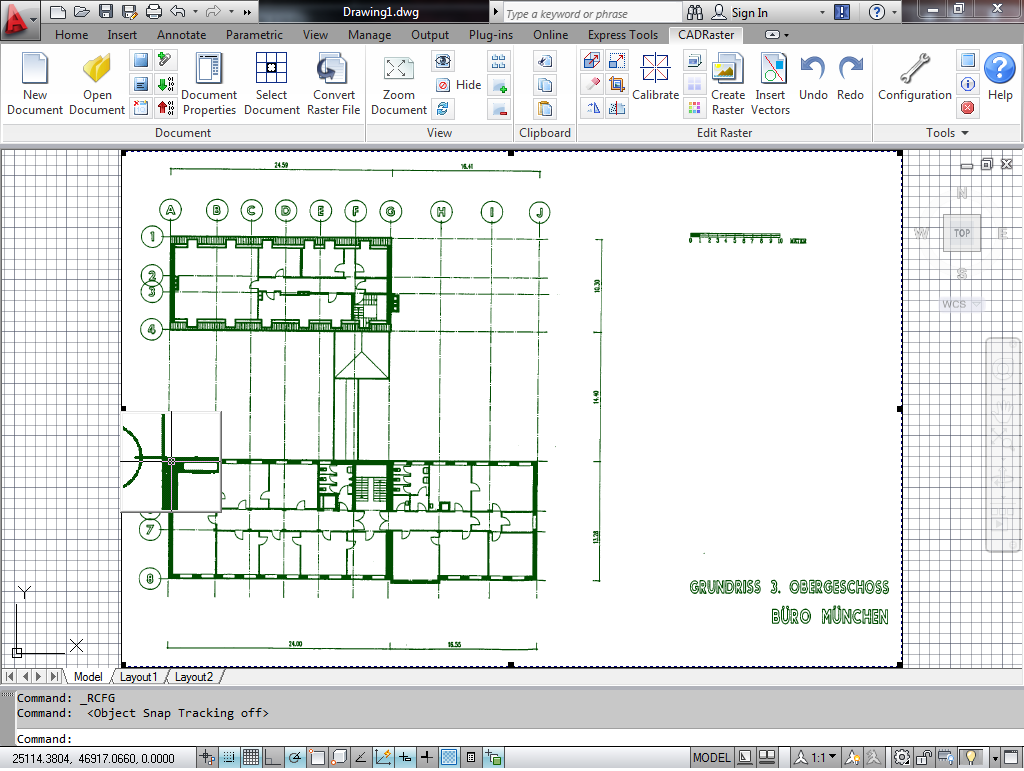
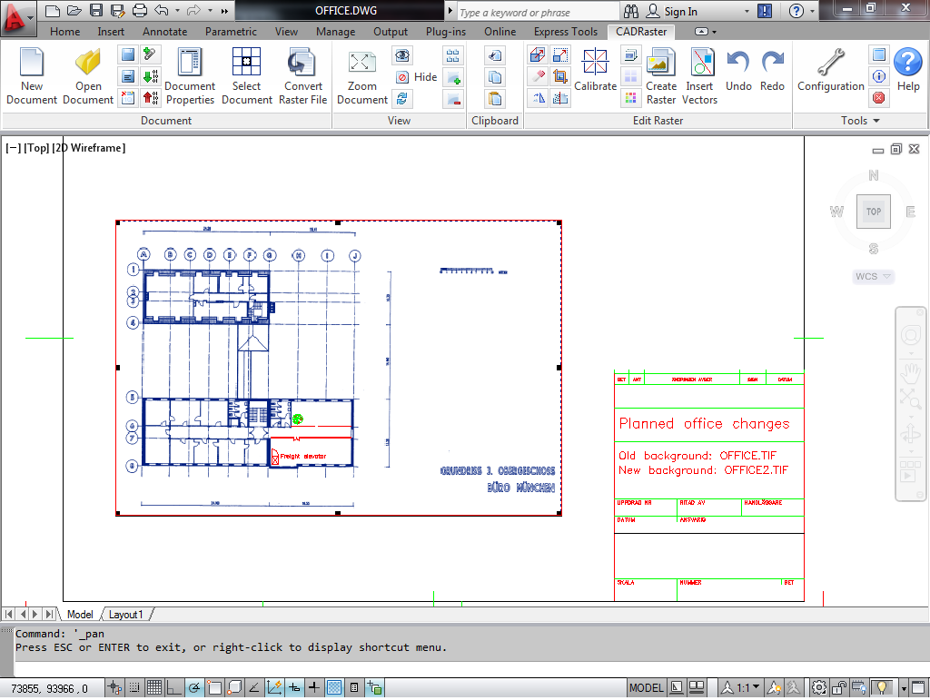
click the AutoCAD’s Open button and choose the office.dwg drawing from the CADRaster’s DOC subdirectory.
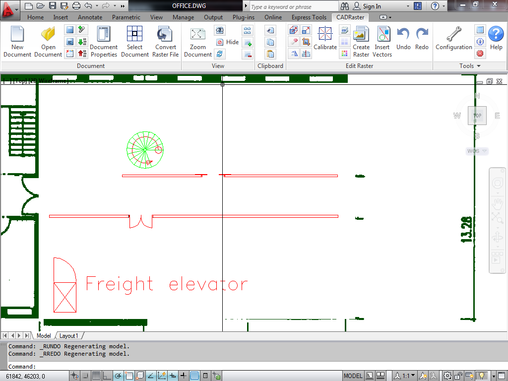
AutoCAD should show a DWG with a complete drawing border, some walls, doors and other objects drawn over the scanned background.
If you don’t see the entire drawing, as shown in the figure below, use the AutoCAD’s ZOOM/ALL command.
You can, of course, use the standard AutoCAD’s drafting commands, symbol libraries, or complete applications to create your own drawings, or to add something to our office.dwg.
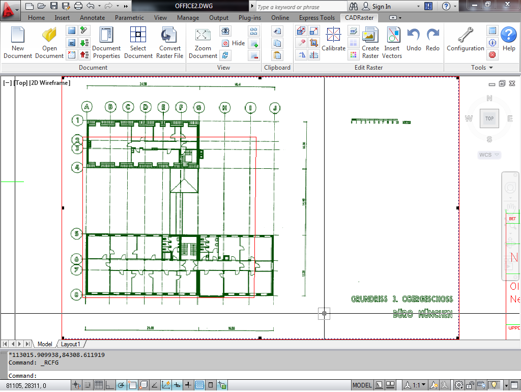
The new walls and doors are meant to replace the old ones that must be removed from the background raster image. In order to see how this should look like when done, click the Open button on the CADRaster toolbar and choose office2.tif from the CADRaster’s DOC subdirectory. The combination of office.dwg and office2.tif makes up a hybrid document that shows the intended modifications of the building floor. Both raster and vector components of the hybrid drawing may be printed together. The next section describes how to get the modified office2.tif.
CADRaster provides tools to control and modify background raster images.
You can use the RDoc command and its subcommands to modify various parameters of the raster image,
the RMove command to change its insertion point (origin), and the RClear command to clear chosen rectangular or polygonal areas of raster images.
Other raster editing commands are: RPage, RRotate, RMatch, RCopy, RCut, RPaste and RFilter.
As at the beginning of the previous section, open the office.dwg vector drawing (using AutoCAD’s Open) and the office.tif scanned drawing (using CADRaster’s ROpen).
Use AutoCAD’s ZOOM/WINDOW to show the right lower corner of the floor, where the new walls and doors have been drawn.
Click the Clear button on the CADRaster ribbon,
choose Polygon and Opaque from OTM options and define a polygon that fences around those parts of the background drawing that need to be removed, as shown in the figure below.
While defining the polygon, you may use OTM activated by OTM hotkey (default: Ctrl+RightClick).
Back command, whenever you need to redefine one or more vertices.
After having all vertices defined, click the right mouse button twice to terminate the polygon definition and the command, and accept the clearing operation by clicking the right button once more.
CADRaster edits the image file and regenerates the screen.
Click the Undo button to see the office.tif before the modification.
Then, click the Redo button to see the modified drawing again.
Click the Save as button on the CADRaster toolbar and save the modified background image under a new name, e.g. office3.tif.
CADRaster’s composite document viewer supports a number of raster formats (see the section called “Appendices”) including full-color pictures, e.g. photographs. Similarly to monochrome scanned images, color pictures may be equally well assigned the scale and other parameters that define the image position in the AutoCAD’s world coordinate system.
Start CADRaster and click the Open button on the toolbar.
For File Type choose TIFF and open the photo.tif file from the DOC subdirectory.
Click the Control doc button and inspect the parameters in the Raster Image Properties dialog, as in the figure below.
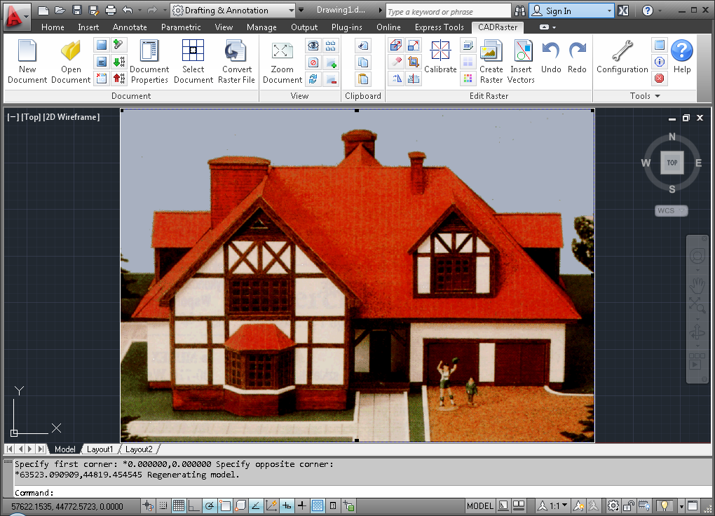
The Effective Image Extents of the photograph on the AutoCAD screen result from the Scale (1:300), Resolution (300x300 dpi), Units (mm) and the Insertion Point (0.0,0.0 mm). Please try to change those parameters in the Raster Image Properties dialog, close it and, after the regeneration ends, check how they affect the extents of the image on the graphics screen.
The background color image can be moved, i.e. its origin changed, interactively on the graphics screen.
Click the Move button on the CADRaster toolbar. Click at a point on the image for which you want to define new coordinates (Base raster point),
and then click where that point should be moved to on the screen (Destination point). The image regenerates at the new position.
To move it back, click the Undo button on the CADRaster toolbar.
You may enter the coordinates numerically. Click the Move button again. Instead of showing the base raster and destination points with the cursor, type:
2500,6700 Enter
0,0 Enter
Once the extents and the origin of the image have been established properly, you may, of course, use all AutoCAD drafting commands to create DWG drawings on the color photograph background.
Whenever you need, e.g. for the reasons of the graphics screen clarity, to take the color picture temporarily off the screen, simply click the Off button on the CADRaster toolbar.
The button changes to On, so that you can bring the background image back, when you need it there.
CADRaster’s capability of handling composite documents is useful while comparing different versions made of the same raster image.
If you have any DWG open, click the AutoCAD’s New button to close it.
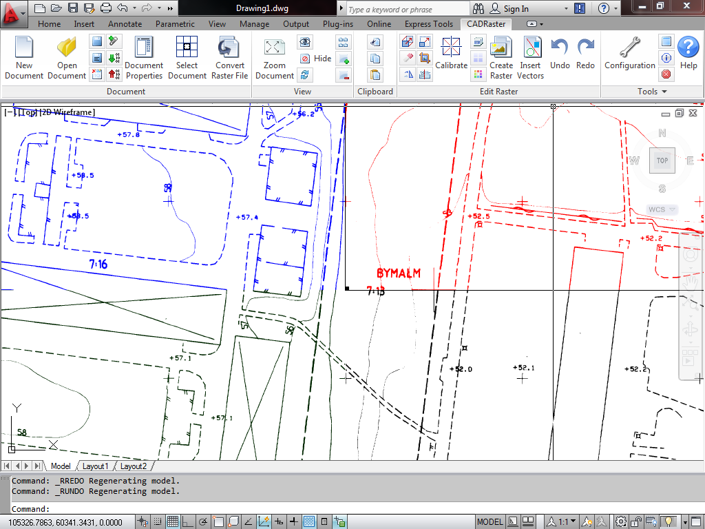
Click the Open button on the CADRaster toolbar or ribbon, for File Type choose Tessel Composite Doc (TCD), and open the electric.tcd document from the DOC subdirectory.
The document should appear on the AutoCAD screen as a scanned electrical drawing in blue, with a few red lines.
The status line of the CADRaster toolbar should read ELECTRIC.TCD (electric.tif, electnew.tif) showing that there are two sub documents in the composite document.
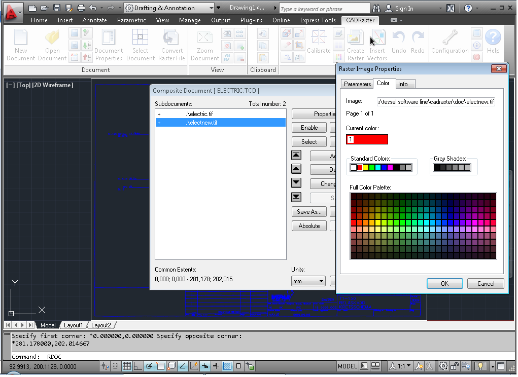
In order to find more detailed information, click the Document Properties on CADRaster ribbon or Control doc button on the CADRaster toolbar and
when the Composite Document dialog pops up, click at the second entry on the Subdocuments list, so that electnew.tif is highlighted.
Click the Properties... button to see that image parameters.
Click the Color tab to see the page that defines the presentation color for this monochrome raster image (1-red), as shown in the figure below.
Click Cancel to close the Raster Image Properties dialog.
While having electnew.tif highlighted, click the Bring forward button on the right side of the Subdocuments list, so that this drawing’s entry moves to the top of the list.
Click the Select button in order to prepare electnew.tif for editing.
Click the Close button to leave the Composite Document dialog and to regenerate the view of the composite document according to the new order of subdocuments.
The color of the image on the screen will turn red, as the red electnew.tif is now covering most of the blue electric.tif,
except of the small part that has been deleted from electnew.tif and remains visible in blue.
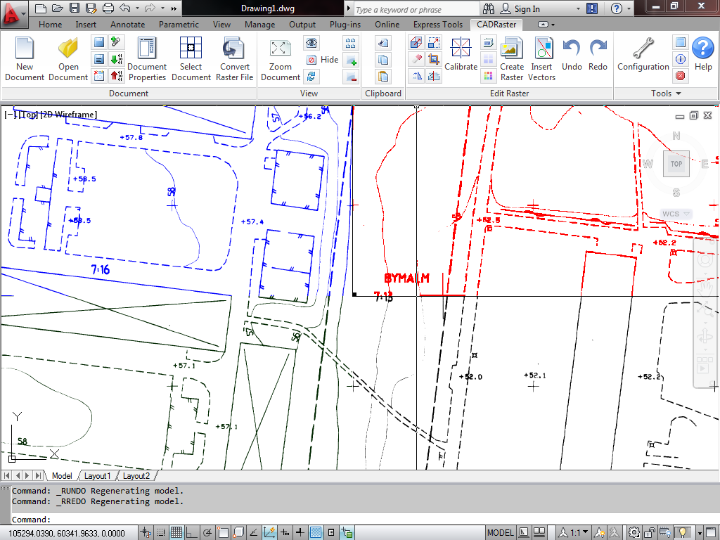
Click the Clear button on the CADRaster toolbar or ribbon
(if the command line mentions Polygon, use OTM and switch to Rectangle, check if the Opaque mode is selected) and choose a rectangular area of the red image to be cleared.
Accept the clearing operation and watch as another part of the blue image underneath gets uncovered.
Close AutoCAD and CADRaster without saving the changes made to the ELECTRIC.TCD document, which also cancels all changes made to the sub documents.
As we have shown in the previous section, CADRaster can operate on composite documents that consist of a number of sub documents. A composite document itself may be seen as a list of links (path names) to files that contain raster or, optionally, vector drawings.
In order to create a sample composite document, start CADRaster and click the Document Properties button on its ribbon or Controll doc toolbar.
The Composite Document dialog that pops up shows the empty Subdocuments list and all command buttons grayed, except Add.
Click the Add button, choose the CADRaster’s DOC subdirectory and the File Type TIFF in the Add Document File(s) dialog;
select four (4) files townmap1.tif ... townmap4.tif and click the Open (OK) button.
The selected files will be added to the Subdocuments list, as shown in the figure below.
The image will be regenerated after you close the Composite Document dialog and click the Zoom whole doc button on the CADRaster toolbar.
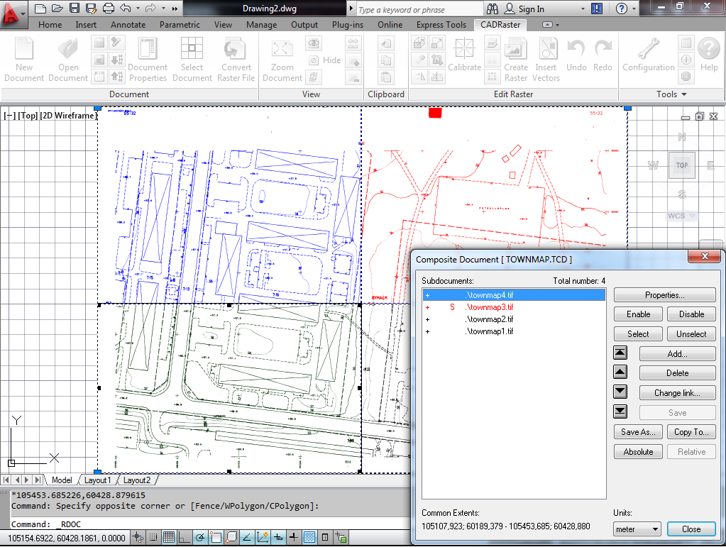
The composite document inherits its Units from the first added subdocument’s TAF attribute file (townmap1.taf),
and its Common Extents represent the combined area of all subdocuments.
Click the Save button on the CADRaster ribbon or toolbar and save the UNNAMEDx composite document as map.tcd, so that the existing townmap.tcd is not overwritten.
In the preceding sections we were modifying single raster images that were selected for editing operations automatically, as the Auto select single file documents configuration option has been checked. Whenever CADRaster operates on a multi-file composite document, the sub documents to be affected by the editing operations must be selected by the user.
Click the Open button on the CADRaster ribbon or toolbar, for File Type choose Tessel Composite Doc (TCD), and open the townmap.tcd document from the DOC subdirectory.
Note that CADRaster’s editing buttons, like Clear, Move, etc., are disabled (grayed).
The CADRaster toolbar’s status line should show TOWNMAP.TCD (townmap4.tif, townmap3.tif, ...), as to identify the opened document and the nothing selected for editing status.
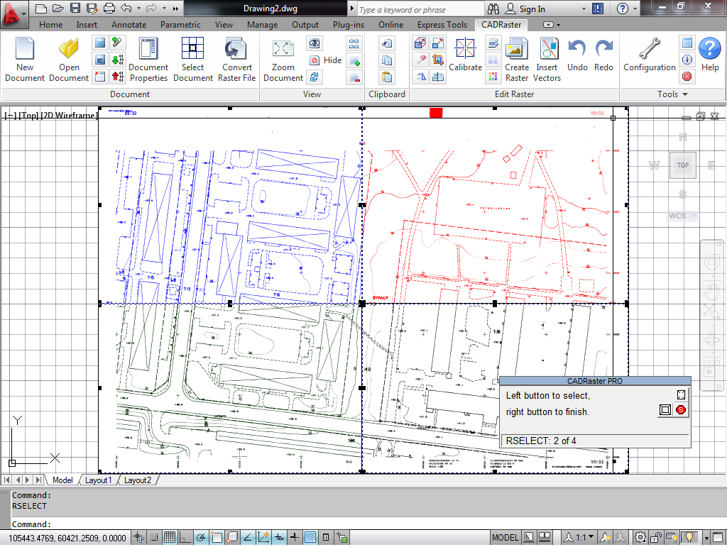
Click the Select Document on ribbon or Selecting on toolbar button and, after the subdocuments’ extents are shown and the toolbar changes to the RSELECT status dialog,
hold down the Shift key and click the left mouse button at the upper left and then at the lower right segment of the map on the screen.
The selected segments (subdocuments) will be marked by the rectangles of their viewports drawn with rectangular tracker marks at their corners and midpoints, as shown in the figure above.
Click the right mouse button to finish the selection process. The CADRaster toolbar’s status line should now read Selected: 2 of 4, and the editing buttons should now be enabled.
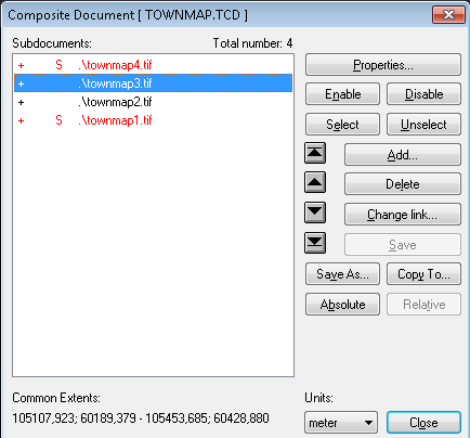
If you want to check the selection status on the Subdocuments list, or it is more convenient to do the selection there, click the Document Properties on CADRaster ribbon or
Control doc button on the CADRaster toolbar.
The Composite Document dialog will show the two selected entries of the Subdocuments list, townmap4.tif and townmap1.tif,
preceded by the S selection mark and displayed in red, as shown in the next figure.
You may combine the both methods of selecting: graphical - using the Select Document\Selecting button and clicking at the images on the screen,
and from the Subdocuments list - using the Document Properties or Control doc button,
highlighting the drawings on the list and clicking the Select and Unselect buttons in the Composite Document dialog.
Close the Composite Document dialog, click the Clear button on the CADRaster ribbon or toolbar.
Define a large rectangle around the center of the map, so that it includes portions of all four (4) segments of the map. Accept the clearing operation.
After the image regenerates, you should see that the editing operation has affected only the two (2) selected images, leaving the others unchanged.
Click the Undo button on the CADRaster ribbon or toolbar. The last editing step will be cancelled for both selected images.
Click the Selecting button again, and click Esc (or the right mouse button without selecting anything this time).
CADRaster will return to the nothing selected state, the toolbar’s status line will show the document name, and the editing buttons will get disabled (grayed).
Keeping subdocuments in separate image files and having them logically connected in a single TCD document is a recommended way of working and should be used whenever possible. Sometimes however, a need may arise to merge selected subdocuments into a single raster file, e.g. in order to make the combined images available to applications that do not support composite documents.
Open TOWNMAP.TCD and select two subdocuments, as described in the previous section on Selecting and controlling subdocuments.
Type RMerge command on the keyboard and type a new file name for the merged file in the Merge file dialog box that pops up on the screen, e.g. maps1&4.tif.
After having the merge operation completed, open the newly created file. It should contain the selected subdocuments merged into one file, as shown below.
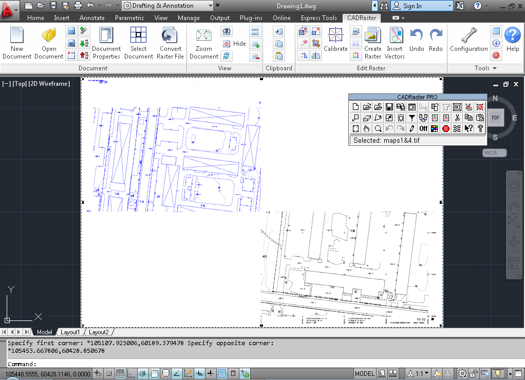
The RMerge command is particularly useful when merging a larger number of subdocuments selected from a complex TCD file with dozens or even hundreds of subdocument links.
It is worth appreciating that each subdocument preserves its position in the world coordinates system, so, if the source subdocuments were calibrated, the merged result will be equally well calibrated without any additional actions.
In CADRaster sessions AutoCAD drawings (DWG) may appear in the foreground, when opened by AutoCAD for editing and optionally, in the background, when viewed by CADRaster either as single drawings or as subdocuments of a composite document.
Start CADRaster, click the AutoCAD’s Open button and choose the parcels.dwg drawing from the DOC subdirectory.
The DWG drawing shows two (2) hatched polygons and a text informing that its background map is a composite document townmap.tcd.
Click the Open button on the CADRaster ribbon or toolbar, for File Type choose Tessel Composite Doc (TCD),
and open the townmap.tcd document from the DOC subdirectory.
Click the Document Properties on ribbon or Control doc button in order to see the Subdocuments list.
At this time the session consist of the parcels.dwg, that is opened by AutoCAD and shown in its title bar, and TOWNMAP.TCD (townmap4.tif, ..., townmap1.tif),
that is opened by CADRaster and shown in its status line and in the Composite Document dialog.
In order to create a single document that contains references to all background images and to the foreground DWG drawing, we are going to include a reference to the current DWG drawing in the composite document.
Close the Composite Document dialog.
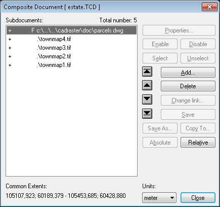
Click the Add DWG to TCD button on CADRaster ribbon or Add foreground to document button on a toolbar and click the Document Properties or Control doc button to open the Composite Document dialog again.
At this time you should see a reference to the DWG file added to the list of subdocuments.
The F flag denoting that this is a foreground drawing should precede its pathname. Close the dialog.
Click the Save as button on the CADRaster ribbon or toolbar and save the modified composite document as estate.tcd.
Close the CADRaster session and start the program again. Click the Open button on the CADRaster toolbar and open the newly created estate.tcd.
Note that parcels.dwg is automatically opened for foreground editing by AutoCAD. The background is provided by the remaining subdocuments of estate.tcd, i.e. townmap4.tif, ..., townmap1.tif.
CADRaster’s Magnifying Glass tool provides quick and transparent access to a detailed view of the raster background in the neighborhood of the current cursor position. Magnifying Glass is an important support tool for snap to raster functions, as described in the next section of this manual, and for this reason it is controlled by the same dialog. It is, however, very useful also independently from snapping and may be used for quick viewing of image details and precise manual positioning of the cursor on the raster background while executing AutoCAD and CADRaster commands.
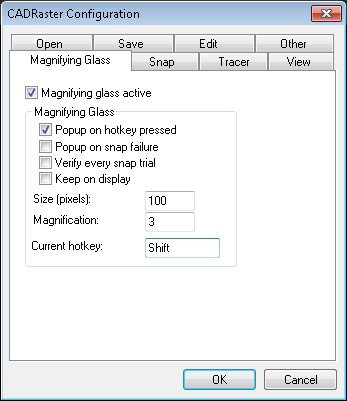
Start CADRaster and open office.tif. Click the Configuration button and choose the Magnifying Glass tab.
Check the Magnifying Glass active and Pop up on hot key pressed options - this will let you pop up Magnifying Glass by clicking Shift.
Default values for Size (100 pixels) and Magnification (3 times) should do fine for most images, but you may, of course, change them as needed.
If you are using Shift+RightClick for AutoCAD pop up menu, it may be wise to change the Magnifying glass hot key to something else, say F12.
Use AutoCAD’s Line command to draw an outline of the scanned floor drawing, or to connect any specific points of it.
This practically forces you to use AutoCAD’s ZOOM/Window and CADRaster’s Zoom whole doc commands repeatedly, which is certainly not convenient.
Now repeat the same exercise using Magnifying Glass.
Click the CADRaster’s Zoom whole doc button to show the entire document.
Start AutoCAD’s Line command and place the cursor at the intended beginning of the line on the raster background.
Click the Shift key (Magnifying Glass hot key).
The Magnifying Glass pops up showing an enlarged neighborhood of the cursor position, an image of the AutoCAD’s cursor at the moment of pressing Shift,
and a small cross cursor that you may use to define a point within the Magnifying Glass window.
Place the cross cursor precisely on the enlarged raster background and click left mouse button to define a point.
The AutoCAD’s Line command receives the point’s coordinates, the Magnifying Glass window disappears, and you may proceed to define next point.
Please notice that you may close the Magnifying Glass window without defining a point simply by moving the mouse cursor outside of it.
Magnifying Glass is equally usable while defining those CADRaster commands that require precise graphical input.
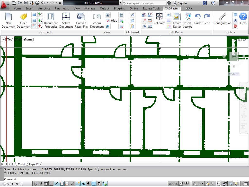
ZOOM/Window to show the lower half of the office.tif image. Click the Clear button on CADRaster toolbar.
Try to clear interiors of rooms located next to the stairs.
It is much easier to define rectangle or polygon corners when you click Shift and define each point through Magnifying Glass.
When you need to have a better control over the exact position of points that are being entered through Magnifying Glass, check the Keep on display option on the Magnifying Glass tab of the CADRaster Configuration dialog.
This will make the Magnifying Glass pop up window wait on the screen until you click the right button to accept the entered point position.
Press Esc to close Magnifying Glass without defining a point.
Drafting on the background of scanned images can be made more convenient and productive with help of CADRaster’s selective Raster snap function. Snapping to raster features may be enabled permanently or transparently called from within AutoCAD or CADRaster commands.
Note
Please remember that in 64-bit version of CADRaster, raster snaps have been replaced by intelligent snaps so snap options are set automatically.
Start CADRaster and open office.tif.
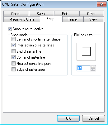
Click the Configuration button on CADRaster ribbon or Configure button on CADRaster toolbar and choose the Snap tab.
Check the Snap to raster active and Magnifying Glass active options.
Check the following Snap modes: Intersection of raster lines and Corner of raster line.
Make sure that the Magnifying Glass options Verify every snap trial and Keep on display are checked.
Increase Pickbox size to 14, or so. Click the OK button.
The Raster snap pickbox will be added to the AutoCAD’s cursor, indicating that the continuous snap to raster mode is active.
Click the AutoCAD’s ZOOM/Window button.
Click the Suspend mouse input button (or press Ctrl+S) to release the mouse cursor control to AutoCAD,
choose a zoom window containing the right lower corner of the building together with dimensioning lines.
Click the Suspend mouse input button (or press Ctrl+S) again to resume the snap to raster mode.
(This kind of suspending is not needed to perform AutoCAD’s commands that do not require mouse coordinate input; e.g. to ZOOM/In simply click the appropriate button or type the command.)
While having the snap to raster mode active, type AutoCAD’s command Dist.
Place the pickbox around one end tick of a vertical dimension line labeled 13.20 and click the left mouse button.
The Magnifying Glass window pops up to show the result of snap to the intersection point.
If the snapping cross position is correct, accept it by a right mouse button click.
The corrected point coordinates will be transferred to the Dist command.
Otherwise, place the cursor correctly inside the Magnifying Glass window and click the left mouse button. Accept the adjusted position by right click.
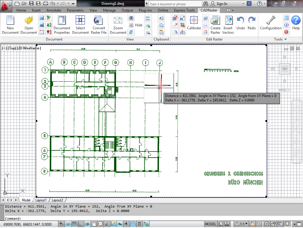
Repeat the same action for the other end of the dimension line. When we have done it, the measured distance was 14348 (mm), quite different from the 13.20 (m) label. You will get much better result when using office4.tif that you may have created doing the resizing or matching exercise described in sections below.
The usability of various snap modes depends heavily on the features of background raster images. It is recommended to use the Magnifying Glass to verify snap results visually and to correct it manually, whenever the automatic snap result is not satisfying.
Lines and other entities of color images can be made of many colors in different shades, so some kind of filtering scheme is needed in order to let the snapping mechanism properly determine the boundaries or raster lines and areas. CADRaster offers an interactive Raster snap color filter tool that lets the user define and examine adequate color interpretation, before it is used for snapping purposes.
Start CADRaster and open grudz.tif, a color map that contains some features, like roads and forest areas, suitable for color-sensitive snapping.
Click the Filter button on CADRaster toolbar or select Filter colors from CADRaster ribbon.
Choose a color sample area containing a junction of main roads that drawn in red (if the pickbox size is inadequate, use OTM/Snap... and choose a different one).
The Snap/Trace Colors Filter dialog shows two windows, Colors sample and Filtered image example, that allow for further zooming in and out, if necessary.
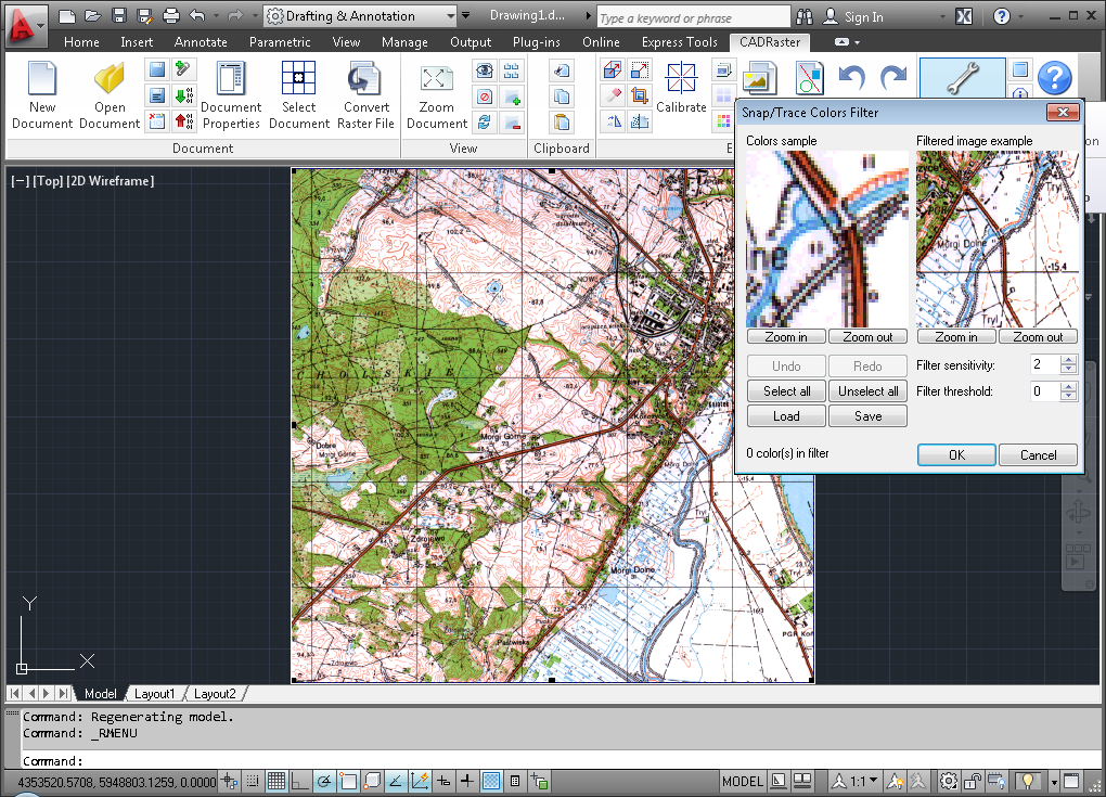
In the Colors sample window click those pixels in different shades of red that belong to the main road line. All pixels of the same color get marked by white dots, the counter of colors in filter increments, and the Filtered image example window shows the filtered image; clicking inside this window toggles between color and black and white presentation. Clicking once more at a selected pixel in the Colors sample window removes its color from the filter; you may also use additional control buttons.
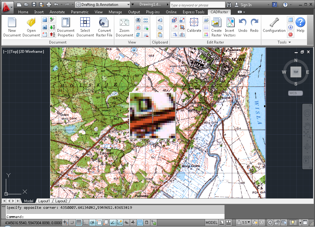
After having a color filter defined, click the OK button to close the Snap/Trace Colors Filter dialog, then activate snap and set Magnifying Glass options. Try snapping to different features, the centerline or intersection of the roads, or the edge of the forest areas.
Scanned grudz.tif is a full color image, so a good filter definition for the main roads may require up to 12 colors, the forest areas drawn in various shades of green, may take more than 20 colors, possibly collected from a number of samples. Needless to say, your snapping results will be only as good as the colors filter’s ability to retrieve a complete image of interesting entities, and only those, from the background. Furthermore, some color images will simply not contain any suitable entities to snap to.
Filter colors selections may be saved and loaded when needed again using Save and Load buttons in the Snap/Trace Colors Filter dialog.
Cropping may be the most common raster editing operation, as the scanned images usually contain oversized margins, usually filled with dirt, that need to be cut off. Equally often you might need to remove old drawing borders and other parts that happened to be located closer to drawing’s margins.
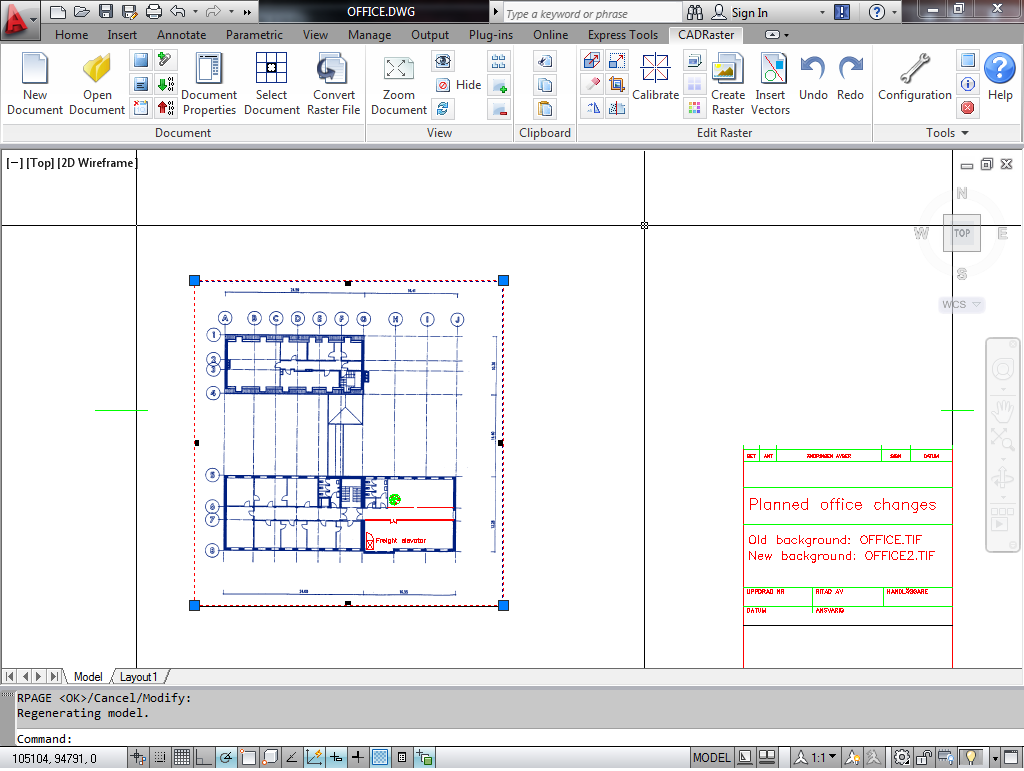
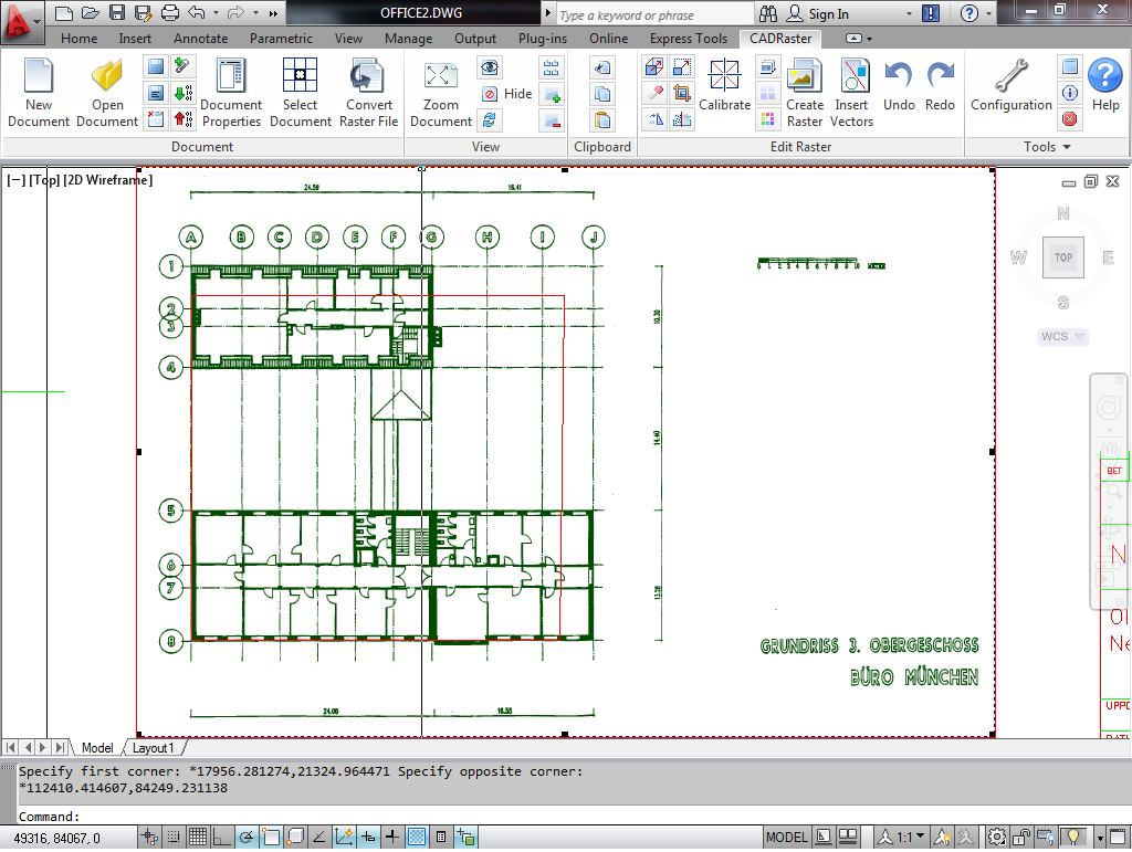
Click AutoCAD’s Open button and choose office.dwg, and after that, click CADRaster’s Open button and choose office2.tif.
Click AutoCAD’s Zoom all button, if necessary, and you should see a hybrid drawing as below.
Suppose that the only part of the scanned drawing that you need for your project is the floor shown between dimensioning lines. Texts on the right side may be removed and the scanned image extents may be actually smaller.
Click the Crop, Define Page on CADRaster ribbon or Crop/Page button on the CADRaster toolbar and choose Crop rectangle from OTM options.
(If OTM does not pop up, it means that the command has been used before, so you must use OTM hotkey (default: Ctrl+RightClick) to get OTM on the screen).
Define a rectangle encompassing this part of the scanned drawing that you want to have and accept the Crop rectangle command with a right click. All unwanted parts get cut off and the scanned image will get smaller, as shown below. Click the CADRaster’s Undo button to reverse the changes, or exit AutoCAD/CADRaster without saving anything.
In one of previous exercises we have used the background of office.tif in order to create a new design by clearing some areas and adding new elements drafted in office.dwg. The resolution, scale and orientation of the background image were correctly defined, but the original drawing may be not to the scale and the scanning process may have produced a skewed image with distorted size and proportions.
Start CADRaster, use AutoCAD’s Open command and choose office2.dwg.
This vector drawing contains a polygon drawn to the nominal dimensions of an office building.
Click CADRaster’s Open button and choose the office.tif file from the DOC subdirectory.
You will easily see the difference between vector-defined outline and the corresponding scanned image, as shown in the figure below.
You may use AutoCAD’s command Dist to check that the distances on the scanned image are not according to horizontal and vertical dimensions that are shown on the image.
If the scanned image is needed as a background for any kind of precision drafting, it must be dimensionally matched to its reference dimensions, and that may require independent X & Y resizing.
Before we resize the image, however, it is recommended that the scanned image is aligned either horizontally or vertically.
In this exercise we will use Magnifying Glass,
so click the Configuration button and check on the Magnifying Glass tab Magnifying Glass active, Pop up on hot key pressed and Keep on display options.
To avoid conflicts with AutoCAD’s osnaps, define F12 as Current hot key - simply select it in it's box and press F12.
Make sure that office.tif is selected for editing.
Click the Rotate button on CADRaster ribbon or Rotate/Align button on CADRaster toolbar.
If necessary, use OTM hotkey (default: Ctrl+RightClick) and choose OTM option Align.
In order to align the whole image so that the left wall is vertical, define two points at its edge.
First, place the cursor at the outside edge near the left lower corner of the building, click F12 (Magnifying Glass hot key) to pop up Magnifying Glass,
click exactly at the wall’s edge and if the picked point position looks good, accept it with a right mouse click.
Repeat it for the Second point of reference line at the left upper corner of the building.
Accept the Vertical alignment and the Align command with right clicks.
The visible effect of alignment will be rather small, as the image was skewed only a little, but you may notice that some horizontal and vertical raster edges are now sharper.
Save the aligned raster image as office4.tif.
Next, we will move the raster image, so that its left lower corner corresponds to the left lower corner of the reference vector data.
Click the AutoCAD’s ZOOM/Window button and choose a new window around the left lower corner of the building, as shown in the figure below.
Click the Move button on CADRaster ribbon or toolbar.
Use the Magnifying Glass as before to define Base raster point exactly at the intersection of reference lines at the left lower corner of the building.
Then, press Shift+RightClick, choose AutoCAD’s Endpoint and snap to the left lower corner of vector reference polygon to define Destination point.
Accept the Move operation by a right click. The left lower corner of the building’s wall should move to the desired position.
If you are not satisfied with the result, click the Undo button on CADRaster ribbon or toolbar and repeat the Move command.
The scanned image, now aligned and moved to the correct position, is apparently too large when compared to its reference vector data.
Click the Match or Resize button. If necessary, use OTM hotkey (default: Ctrl+RightClick) and choose OTM option Resize.
The left lower corner is at the correct position already, so we will use it as Base raster point - its position will be not changed by the Resize operation.
Press Shift+RightClick, choose AutoCAD’s Endpoint and snap to the left lower corner of vector reference polygon again,
this time as the easiest way of defining Base raster point that we have moved there previously.
To define Raster reference point use Magnifying Glass and click exactly at the intersection of reference lines in the upper right corner of the image
(just under the J in a circle sign).
You may now drag the Raster reference point to its Destination point but, since we have the vector reference polygon ready,
the easiest and most correct way is to press Shift+RightClick, choose AutoCAD’s Endpoint and snap to the right upper corner of vector reference polygon.
Accept the Resize command with a right click.
After resizing the scanned image should quite exactly match its vector reference data, so that further drafting on its background may be done directly in AutoCAD’s world coordinates.
Click the Save button on CADRaster ribbon or toolbar.
The Resize procedure described in the previous section is quite simple to understand but not so simple to execute,
since it involves a number of steps, like Align, Move and Resize, which are needed to achieve desired results.
Providing that we have sufficient reference data, the same and even better results may be achieved using just one command
Match that provides the simplest possible interface to powerful Tessel Systems CALIBRATOR.
As in the previous section, open office.tif and office2.dwg. We want to get the best possible match between the four corners of the vector reference polygon and the corresponding corners of the raster image.
Click the Zoom Document on CADRaster ribbon or Zoom whole doc button on the CADRaster toolbar.
Click the Match/Resize button.
Use OTM hotkey (default: Ctrl+RightClick) and choose OTM option Match.
For each corner of the scanned floor drawing define Raster point by placing the cursor close to the corner,
pressing defined Magnifying Glass hot key and picking the intersection of reference lines at that corner, as shown below.
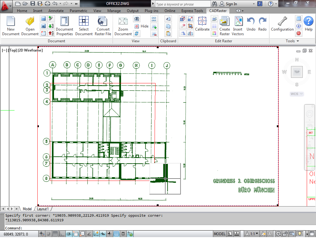
Accept each Raster point by a right click, press Shift+RightClick, choose AutoCAD’s Endpoint and snap to the corresponding corner of the vector reference polygon.
After defining matching vectors for all four corners, accept the Match command by a right click.
After the raster image is recalculated you should be able to see that this simple and quick operation has produced quite a perfect match at all four corners.
Let's try to check what such simple to do a matching operation is worth.
Click the Configuration button on the CADRaster ribbon or toolbar and check the Snap to raster active,
Intersection of raster lines and Corner of raster line options on the Snap tab.
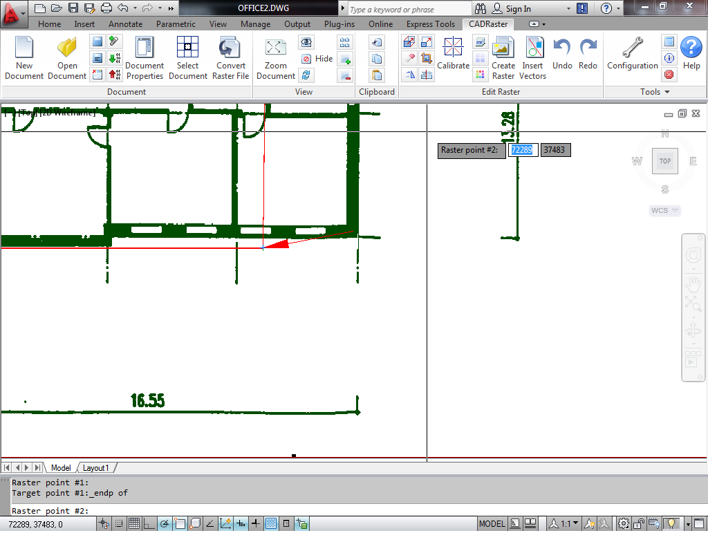
Zoom/window so that the dimensioning line segment on the right lower side of the building is well visible, as shown above.
The dimensioning text on the image says 13.28 (13.28m = 13280mm).
Type AutoCAD’s command dist and left click at the dimensioning line’s ticks placing them inside the raster snap cursor.
Accept each snap with a right click.
AutoCAD reports Distance = 13278.
Definitely not bad a result as for an A4 copy of an A3 drawing that was faxed to Tessel Systems years ago by a German customer, and then scanned on a desktop scanner.
Important
This function works only for CADRaster PRO only
The same CALIBRATOR machinery that has been put to work under deceivably simple cover of the Match command may be unleashed with its full power for more demanding jobs.
Let's try to calibrate a scanned drawing of a building that has more irregular shape.
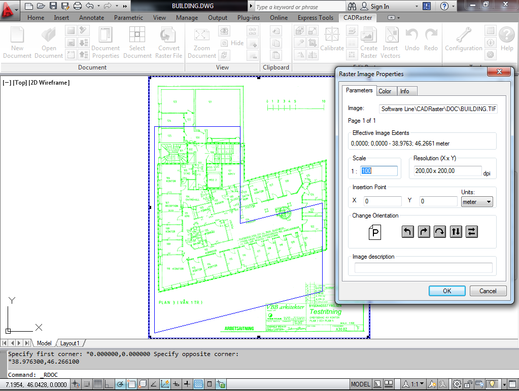
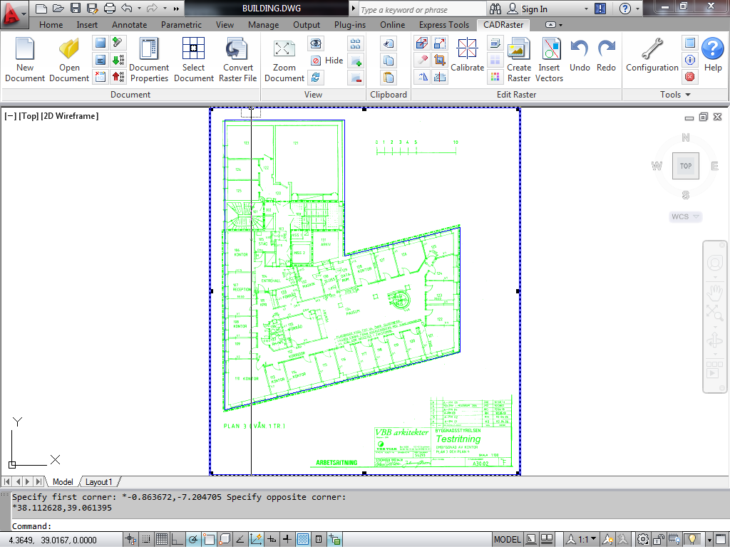
Click the Open button on the CADRaster ribbon or toolbar and choose building.tif.
Open building.dwg in AutoCAD - it contains a red polygon that defines the correct dimensions of the building in the world coordinates.
The scanned drawings is correctly orientated and has a reasonable size since its parameters, like scale and units, have been defined properly, as it may be checked by clicking the Document Properties button, as shown above.
Our task is to match all six corners of the scanned building drawing to the corresponding polygon corners with numerically controlled accuracy.
In order to make the calibration process more convenient we will first move the raster image possibly close to its correct position.
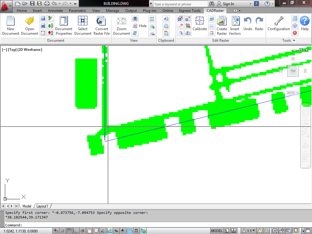
Click the Move button and pick the left lower corner of the scanned drawing as a Base raster point simply by left-clicking at it.
Then move the cursor to the left lower corner of the vector polygon and left-click at it to define Destination point.
This is just a preliminary move which precision does not have any influence on the calibration results, so no snapping or Magnifying Glass is needed.
After moving the raster image it should correspond quite well to the reference polygon, as shown below.
If you wish you might zoom around corners and check that each one shows a different deviation from its correct position.
Click the Calibrate button to show the Raster Calibration Parameters dialog.
Push the Select base entities button, click the selection pickbox at the red polygon and finish selection by a right click.
Push the Add entities based vectors button.
The CALIBRATOR zooms automatically around the first corner of the selected entity with the calibration vector attached to it, i.e. having the target location already defined.
For each target define corresponding Raster point by placing the cursor carefully at the intersection of the outer boundary lines of the building (not the dashed markup line).
You may use OTM hotkey (default: Ctrl+RightClick) to get OTM that lets you change the AutoZoom level or use raster snaps, if necessary.
You may also change the zoom level using the calibration Options button.
If you choose Current, the automatic zooming will be done on the most recently used level that you may change by clicking Zoom in and Zoom out buttons in the Raster Calibration Parameters dialog.
After defining Raster points corresponding to all selected Target points, the Raster Calibration Parameters dialog presents complete numerical information concerning this calibration operation.
Choose the Affine Calibration model from the list and check that Sqrt of mean square error that will remain after calibration is in the range of 0.03m (in world coordinates).
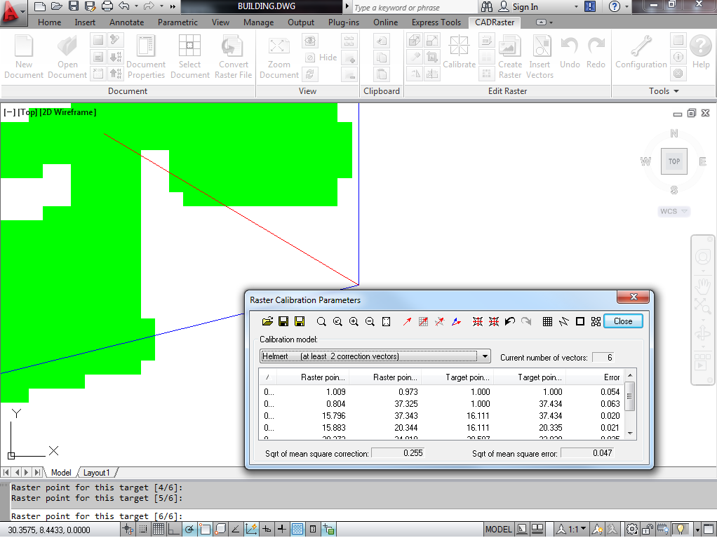
You may push the Net preview button and scroll through the list of Raster and Target points in order to evaluate visually differences between requested
Target points and Calculated points depending on the Calibration model you choose.
If you need to change something, you may delete points from the list or push the Edit vectors button, or double click at a list entry, and change the calibration vectors.
When you are satisfied with the calibration preview, click the Execute button in order to have the transformation applied to the image data.
You may save the calibration report if you wish.
After the calibration is executed you may still keep the Raster Calibration Parameters dialog on the screen in order to examine the results by scrolling through the list of calibration vectors.
If you want to get closer to some point, double click at its entry and Zoom/window as close as its needed.
Then right-click to get back to the dialog and use calibration Undo and Redo buttons to see that point before and after calibration.
If you keep your Net preview button pushed, you should see that the Raster point is being moved by calibration to the end of the Calculated vector.
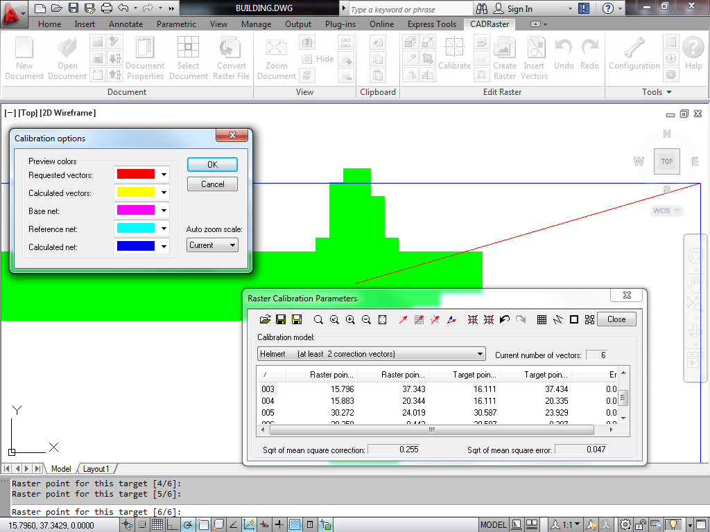
To check or change calibration vector colors, push the calibration Options button.
Exit the Raster Calibration Parameters dialog by clicking the Close button.
Optionally you may save the calibration vectors on file but, if you plan re-using them, remember to save the raster file just before doing the calibration, so that you may repeat the process using the saved vectors.
You may still Undo and Redo calibration changes using CADRaster ribbon or toolbar.
If you want to be able to repeat this exercise without reinstalling demo files, exit CADRaster without saving the modified raster file, or push the Save as button on CADRaster ribbon or toolbar and give it a new name.
Important
This function works only for CADRaster PRO
The same calibration technique described in the section Calibrating images applies to scanned maps. Maybe the most common difference is that while calibrating maps we can use regular networks of reference points more often than for other types of drawings.
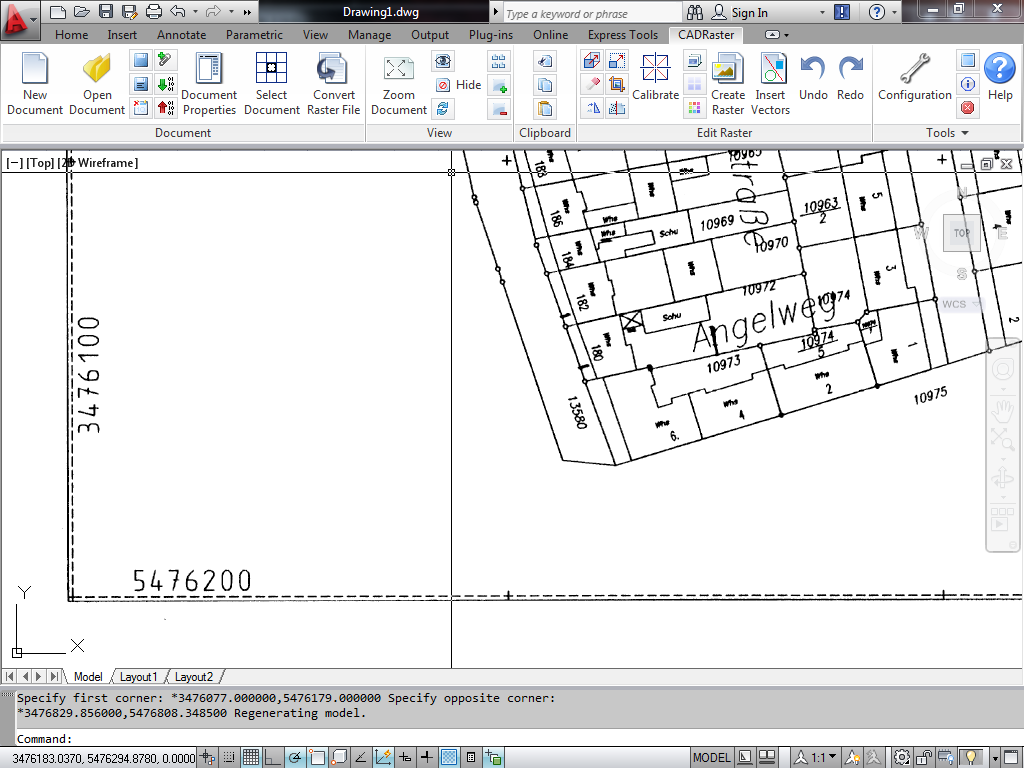
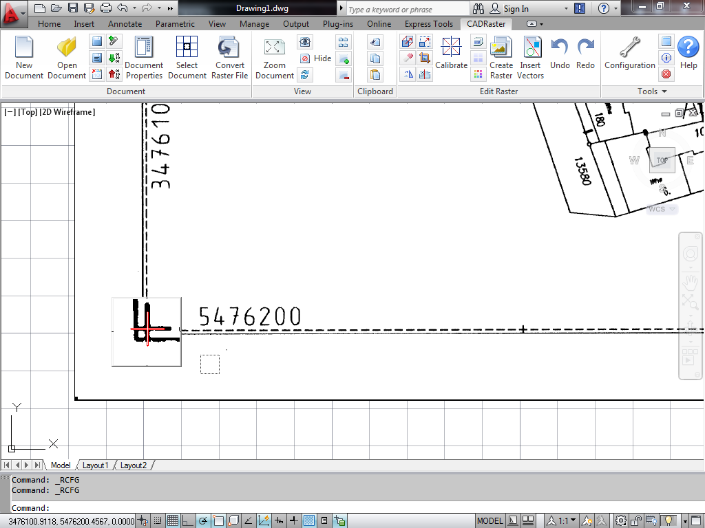
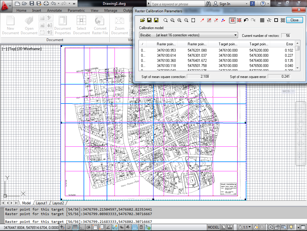
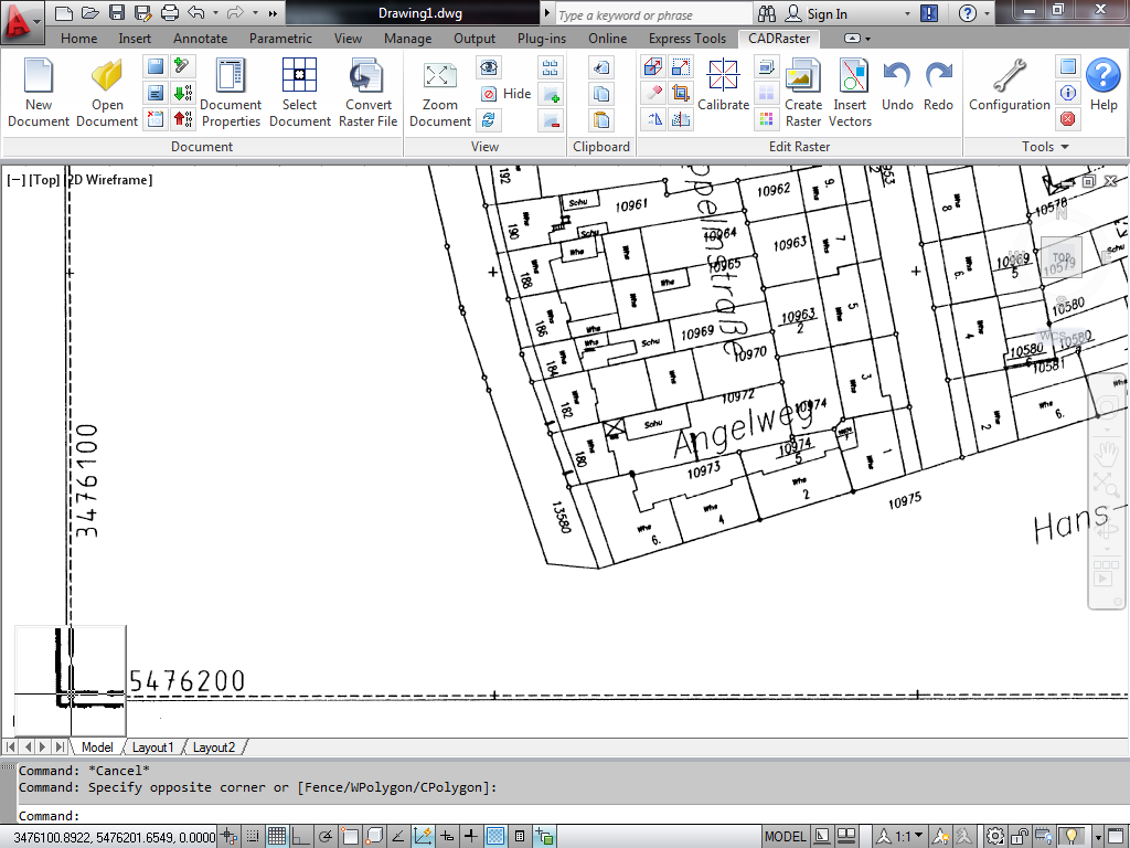
Open hberg.tif file and Zoom/window around its left lower corner, so that the coordinates written there are legible, as shown below.
Click the Move button, pick the left lower corner of the map as Base raster point and type 3476100,5476200 as coordinates of Destination point.
Again, this is just a preliminary move which precision does not have any influence on the calibration results, so no snapping or Magnifying Glass is needed.
Accept the Move command with a right click.
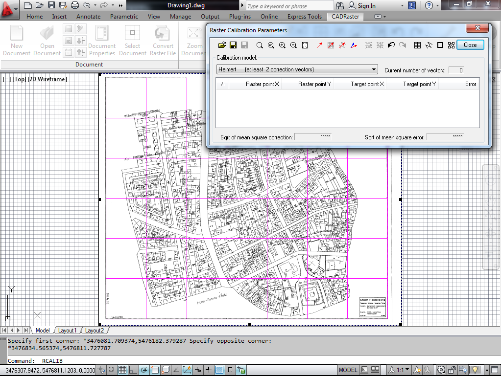
Click the Zoom Document to show the entire map again, and the Calibrate button to show the Raster Calibration Parameters dialog.
Push the Define base net button and type in the Calibration net parameters describing a reference network corresponding to coordinate marks printed on the map as small crosses:
Horizontal vertices number: 8
Vertical vertices number: 7
Single cell width: 100
Single cell height: 100
Net insertion point (x,y): 3476100,5476200
Push the Create button and check if the created net looks as shown below, i.e. in this zoomed out view goes practically right through the marks.
Press the Add net-based vectors button.
The CALIBRATOR zooms automatically around the first corner of the defined net with the calibration vector attached to it, i.e. having the target location already defined.
Since the coordinate marks on the map have the regular form of small raster crosses, we are going to use raster snap to intersection.
Click the Configuration button on CADRaster ribbon or Configure button on the CADRaster toolbar and check the Snap to raster active and
Intersection of raster lines on the Snap tab.
On the Magnifying Glass tab check the Magnifying Glass active, Verify every snap trial and Keep on display options.
For each target define corresponding Raster point by clicking the snap cursor at the corresponding coordinates mark and accept it with a right click.
You may use OTM hotkey (default: Ctrl+RightClick) to get OTM that lets you change the AutoZoom level, if necessary.
Magnifying Glass pops up for every snapped coordinate mark (intersection) and provides instant visual verification. Do not correct errors smaller than half a pixel - it does not have any statistical meaning and often is very subjective. Correct only those points that are obviously wrong, usually due to interference of some other lines with the cross mark, as shown below. You should need to correct no more than 5-6 snaps, and only at one point Raster snap will not find the intersection at all.
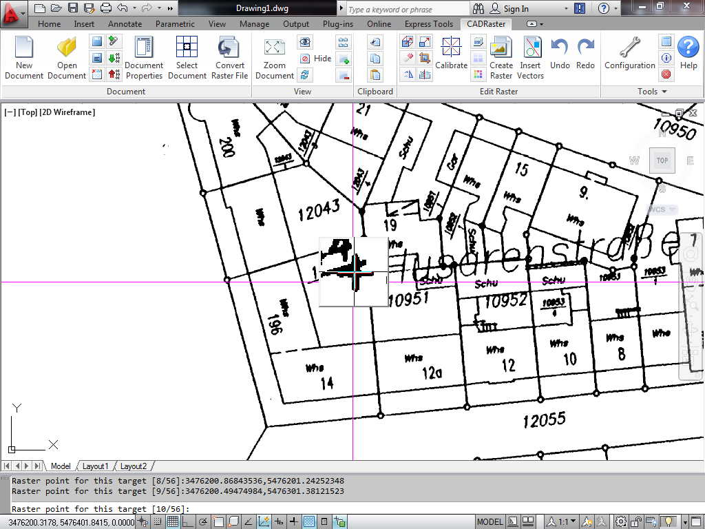
Simply pick a new position for the snap cross in the Magnifying Glass window and accept with usual right click.
If you accept by mistake a wrong point, use OTM hotkey (default: Ctrl+RightClick) and choose the OTM Previous option to go back to it and redefine it.
After defining Raster points corresponding to all 56 Target points of the net, the Raster Calibration Parameters dialog presents complete numerical information concerning this calibration operation. Choose the Bicubic Calibration model from the list and check that Sqrt of mean square error that will remain after calibration is in the range of 0.219m (in world coordinates).
When using Calibration models higher than Bilinear you must look at the calibration preview before executing it.
Insufficient or badly selects calibration data, e.g. colinearly placed Target points, may result in perfectly small residual error and very bad deformation of the raster image between calibration points.
Press the Zoom raster and Net preview buttons.
Calculated net should show only small and smooth deviations from the Reference net, as shown below.
To check or change calibration nets colors, press the calibration Options button.
When you are satisfied with the calibration preview, click the Execute button in order to have the transformation applied to the image data. You may save the calibration report if you wish.
After the calibration is executed you may still keep the Raster Calibration Parameters dialog on the screen in order to examine the results by scrolling through the list of calibration vectors.
If you want to get closer to some point, click at the Zoom in button in the Raster Calibration Parameters dialog.
Then use calibration Undo and Redo buttons to see that point before and after calibration.
If you keep your Net preview button pushed, you should see that the Raster point is being moved by calibration to the end of the Calculated vector.
To check or change calibration vector colors, push the calibration Options button. Exit the Raster Calibration Parameters dialog by clicking the Close button.
Zoom/window around the left lower corner of the map, as at the beginning of this section (you may need to suspend Raster snap by clicking the Suspend mouse input button, and then releasing it after zoom). Snap to raster mark (intersection) at the left lower corner, as shown below.
All coordinate marks on the whole area of the calibrated map will show correct coordinates with accuracy better than 0.2 m in world coordinates.
At 1:1000 scale it means that the calibrated image accuracy is better than 0.2 mm across the entire map.
Important
This functionality is available only in 32-bit version CADRaster PRO
As every specialized tool, CADRaster’s semiautomatic raster lines tracer preferably should be used only for jobs it has been designed for.
One kind of drawings that are suitable for this sort of tracing is isolines maps.
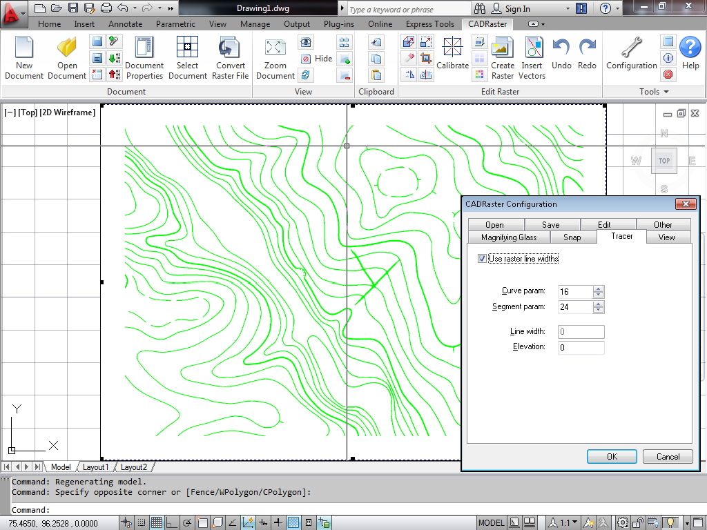
Open isolines.tif, click the Configuration button on CADRaster ribbon or Configure button on CADRaster toolbar and
clear the Raster snap active option on the Snap tab, so it will not interfere with tracer.
Check the Use raster line widths option on the Tracer tab. Close the CADRaster Configuration dialog by clicking OK.
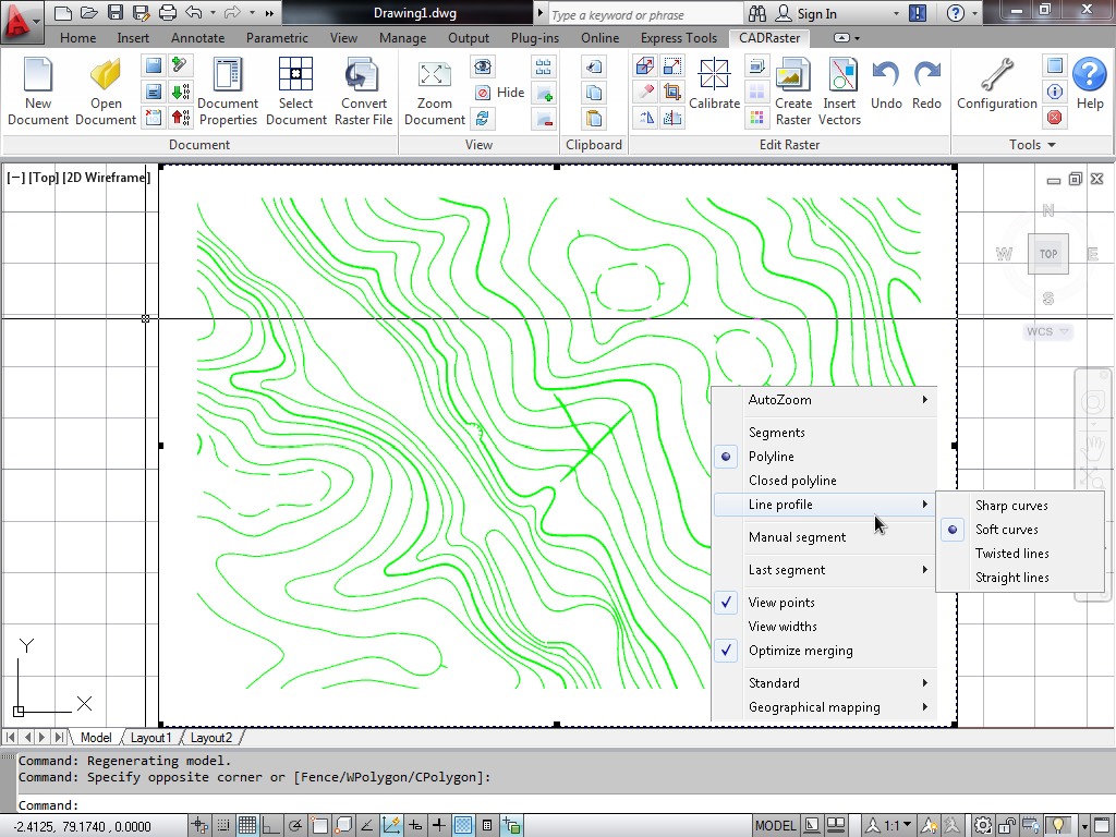
Click the Raster trace button on the CADRaster toolbar and use OTM hotkey (default: Ctrl+RightClick) to select OTM options
Polyline, Line profile\Soft curves, View points and Optimize merging.
Click at the beginning of one isoline and wait until Tracer stops at the end, an intersection or a break in the line.
Click at the next segment to continue the polyline, or RightClick to finish it.
Choose Repeat if you want to trace one polyline after another.
Important
This function works only for CADRaster PRO.
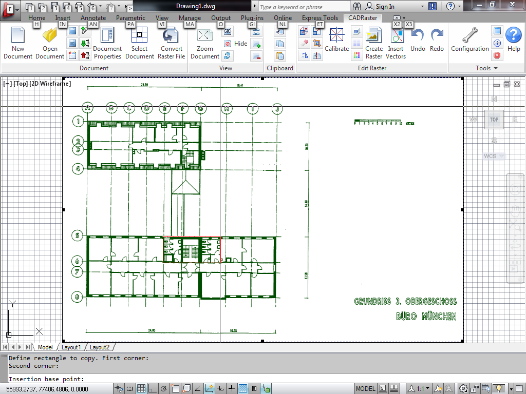
CADRaster Cut, Copy, Paste editing is most often used for moving around selected raster areas within the same image or for transporting them between different raster images.
CADRaster treats rectangular or polygonal areas of raster image in a way similar to AutoCAD blocks.
It operates in world coordinates, defines the insertion base point, and allows for rescaling and rotation while inserting raster blocks.
Open office.tif.
Suppose that we need to create an insert showing the stairway scaled up two times.
Click the Copy raster button on the CADRaster toolbar.
If necessary, use OTM hotkey (default: Ctrl+RightClick) and select the Rectangle and Clipboard OTM options.
Pick corners of a rectangle to copy and the Insertion base point as shown in the figure below.
Right click to accept the Copy raster command .
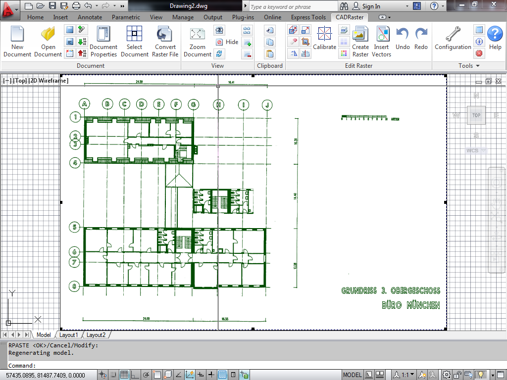
Click the Paste raster button on the CADRaster ribbon or toolbar.
If necessary select the Clipboard OTM option or push the Clipboard button in the Paste from dialog.
Pick an Insertion point in the empty area on the right side of the drawing, type in 2 for
both X and Y scale factors and type Enter to accept no rotation.
Type Enter or right click to accept the Paste raster command.
CADRaster inserts a scaled up image that you have copied to the Clipboard.
Try other options of cut, copy and paste commands, e.g. using polygonal areas and pasting from files.
Important
This function works only for CADRaster PRO
When you need to create new lines or symbols in order to modify the existing raster image, you should use normal AutoCAD drafting commands, symbol libraries etc. The resulting DWG may be then kept as a component of a composite document, as shown before, or vector entities may be inserted into the raster background in order to create a modified single raster file.
Open office.dwg and office2.tif.
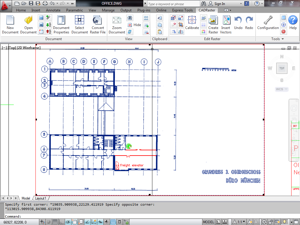
Click the Insert vectors button on the CADRaster ribbon or toolbar.
Pick corners of a rectangle surrounding the new building components drawn in vectors, as shown in the figure below.
Right click to accept the Insert vectors command.
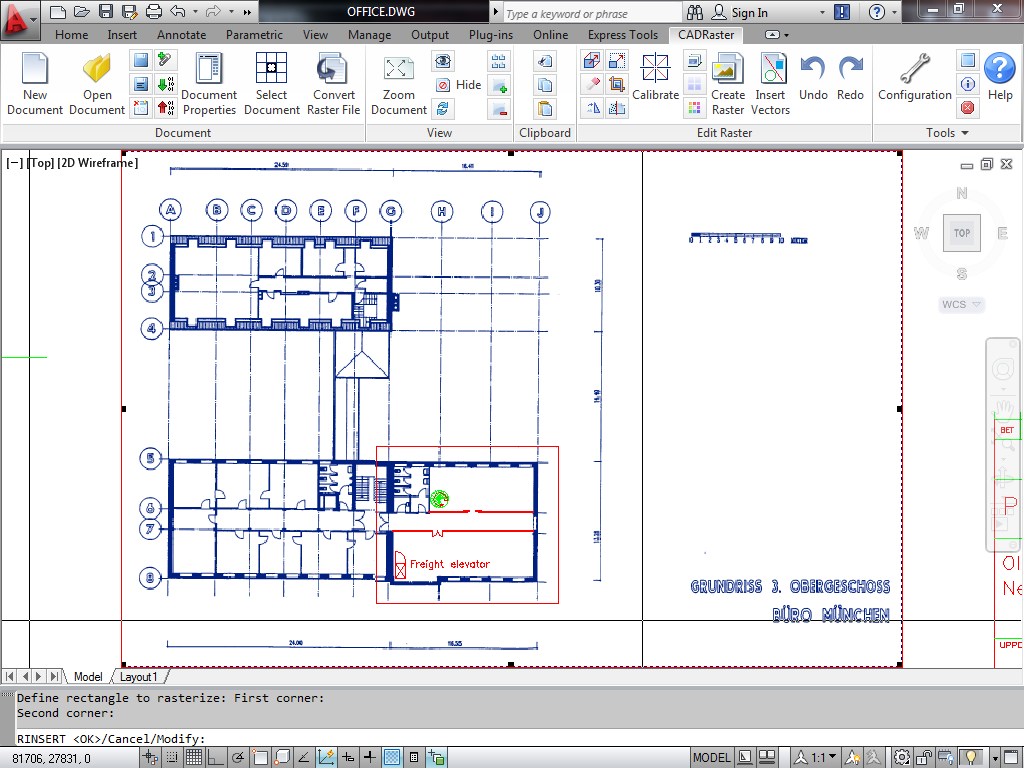
CADRaster uses its CADRaster Rasterize plotter interface to output vectors inside the rectangle, rasterizes them using parameters compatible with the background raster image and inserts the rasterization product exactly under the source vectors. Zoom window to see details of inserted vectors around the Freight elevator text and symbol, as shown in the figure below.
Important
Please remember, that in oder to use this command you need to add a Plotting
output device named CADRaster Rasterizer. See the section called “CADRaster and AutoCAD”.
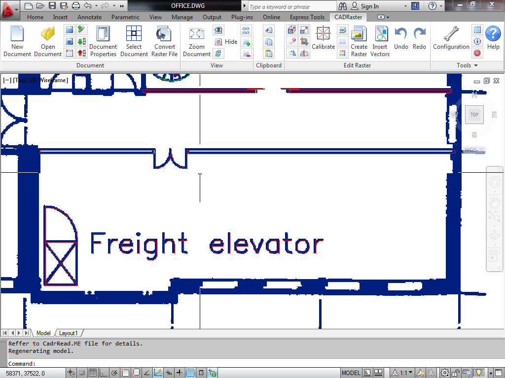
Under close zoom you may need to regenerate the vector drawing in order to get precise shapes - vector lines should appear as centerlines of their raster counterparts. The rasterized lines and texts are thicker, since CADRaster applies its plotter interface pen settings, exactly as if making a plot. The apparent precision of rasterization would be even better for a higher resolution of raster background image.
CADRaster rasterization engine may be used to rasterize whole vector drawings to a selected raster format, either monochrome, grayscale or color. This process is often used to create images of DWG drawings in raster formats that may be easier to distribute or maintain in archiving systems and other applications that do not need to access vector entities.
If any raster file is open, click the Close button on the CADRaster ribbon or toolbar.
Open an AutoCAD sample drawing, e.g. db_sample.dwg or any other 2D drawing from AutoCAD’s SAMPLE subdirectory.
Click the Create raster button on the CADRaster ribbon or toolbar.
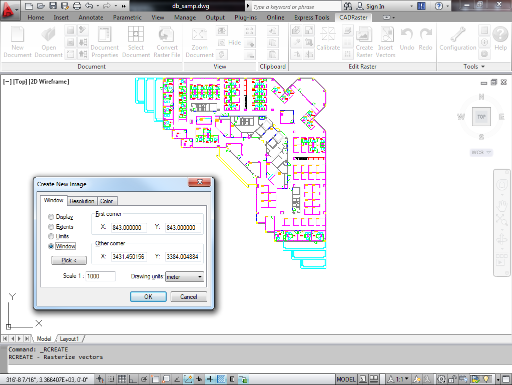
Enter the following parameters into the Create New Image dialog:
Window tab
check Window
type in Scale 1:1000 (if the image is too big it will automatically adjusted).
choose Drawing units meter
Resolution tab
choose Resolution 600 x 600 dpi
choose Image size units pixel (or any other)
Color tab
choose Black and White
Click OK and give the new image file name db_sample.tif.
Choose Compression mode CCITT Group 4 and click OK again.
Important
Please remember, that in oder to use this command you need to add a Plotting
output device named CADRaster Rasterizer. See the section called “CADRaster and AutoCAD”.
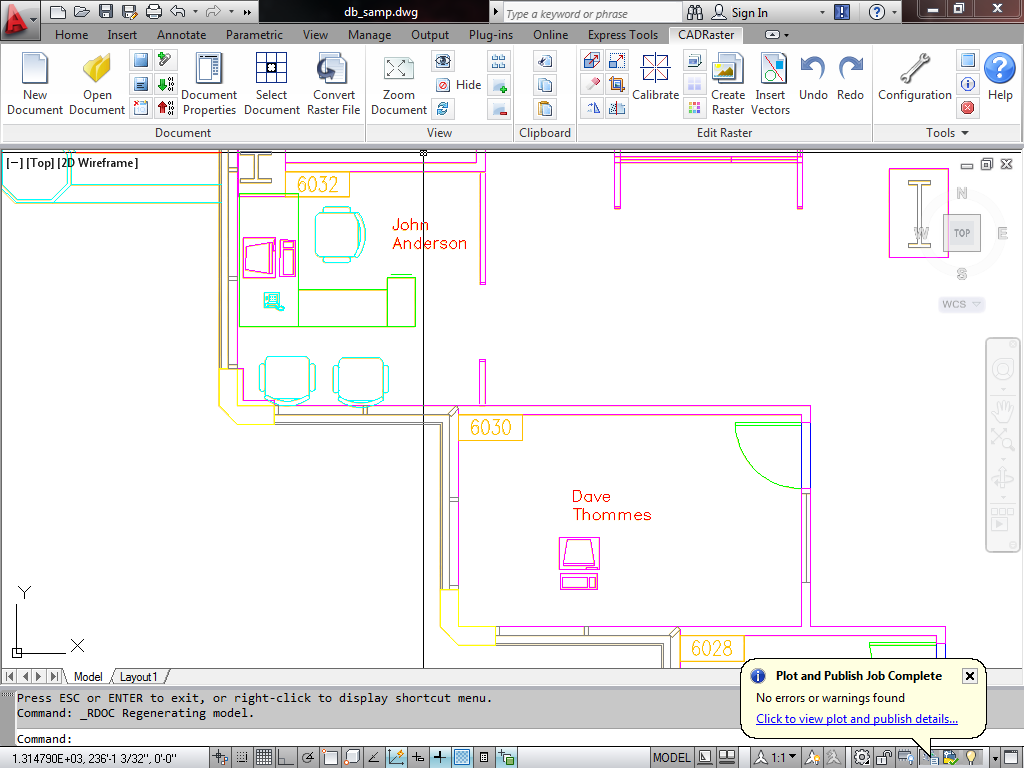
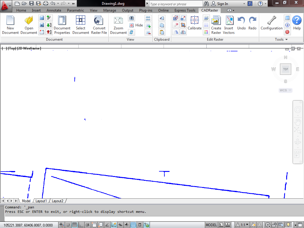
After the rasterization process is completed, open db_sample.tif - it should appear as a background image exactly corresponding to its DWG original, just drawn in thicker black lines.
Click the Document Properties or Control doc button and choose the Color tab.
Select a light color, e.g. 41, so that all vectors may be easily seen on the raster background.
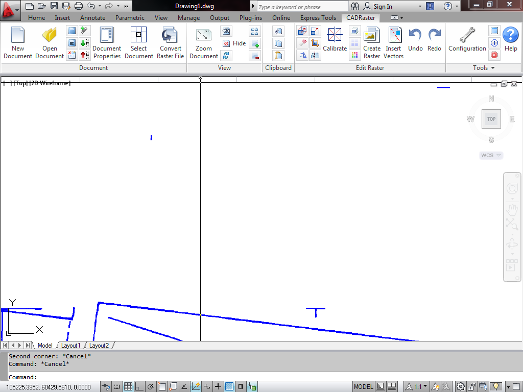
Examine the results of rasterization by zooming closely at some places, as shown in the figure below.
Check the size of db_sample.tif) and compare with db_sample.dwg - due to the high Group 4 compression this high resolution raster image is much smaller than its DWG original.
Scanned drawings often contain areas that require some cleaning in order to remove unwanted spots.
Cleaning of empty parts of the drawing, like margins and bigger white areas, is best done using the RPage or RClear commands.
Removing spots between drawing lines, however, may be done easier through filtering.
Start CADRaster and open townmap.tcd.
Click the Select Document button on CADRaster ribbon, and while holding Shiftleft-click inside townmap.tif (left upper segment)
and townmap2.tif(right upper segment).
Click the right button to accept the selection.
You should see on the screen that there is some dirt that has been scanned in the upper part of both selected subdocuments where it shows as a number of spots, as in the figure below.
Click the Filter Spots button on CADRaster ribbon.
If necessary, use OTM hotkey (default: Ctrl+RightClick) and choose OTM option Filter spots.
Enter a spot size, e.g. 33.
You can also choose a spot sample on the screen to define maximal spot size to remove.
All isolated spots that are not bigger than 33 connected pixels disappear from both selected subdocuments.
You can compare the view before and after filtering by clicking CADRaster’s Undo and Redo buttons a number of times.
The Filter function must be used carefully as to not damage finer details of the image, like small texts or pattern lines.
Spots that are too large to be filtered out must be removed manually using the RPage or RClear commands.
Exit CADRaster without saving the filtering changes made to townmap.tcd subdocuments.
CADRaster provides the Change density function that may be used to change the physical resolution of raster data.
Open townmap.tcd that will be used to demonstrate how this function works.
The Change density function may be used when only one subdocument is selected.
Click the Select Document button, left-click inside townmap2.tif (right upper segment), so that only one subdocument is selected.
Click the right button to accept the selection. ZOOM/Window around the center of townmap.tcd, so that small portions of all four subdocuments are visible.
All subdocuments have been scanned with the same resolution and carefully positioned, so that they match each other nicely along their viewport borders.
Click the Filter Spots button on CADRaster ribbon or Filter on CADRaster toolbar.
Use OTM hotkey (default: Ctrl+RightClick) and choose OTM option Change density.
The X & Y resolution prompts show the current density (200, 200) of the selected subdocument.
Type a much lower value, e.g. 75 for both resolutions and accept the command by pressing Enter.
The townmap2.tif image, after being recalculated at 75 dpi, still appears at the same place in the composite document’s world coordinates and perfectly matches the other neighboring subdocuments.
The raster image is, however, much rougher, as shown in the figure above.
Click CADRaster’s Undo and Redo buttons a number of times and compare how the resolution influences the image quality.
The Density command should be used only when there are specific reasons to change the image resolution.
CADRaster can mix images of different resolutions but some other applications may require that all subdocuments have the same resolution.
Sometimes it may be useful to reduce the resolution in order to get a rougher raster look of the background image, easier to distinguish from vector lines.
Please remember to preserve the original high-resolution data, if you want to use it again.
The Change density command is not reversible and will not restore the original image by changing its resolution to a higher value.
Exit CADRaster without saving the resolution changes made to townmap.tcd subdocuments.
Important
This function works only for CADRaster PRO.
New raster editing library implements improved technology for editing color raster images. It gives you better quality of edited images and greater flexibility in controlling various aspects of image processing modes.
From the Edit tab on Configuration dialog, push the Raster editor settings button. The settings available from the Raster editor settings dialog are grouped in three boxes: Filter type enables choosing among various filter types, Use filter for files defines when to use filtering, an Round bits number to describes how to convert palette images for filtering.
All settings chosen during editing session are stored in INI file.
During resizing, rotating and calibrating color raster images, center of each pixel in transformed image is taken from some position in original image. Since this position generally does not correspond to any pixel center and is placed somewhere between them, the color value of new pixel has to be interpolated in some way from the colors of neighboring pixels.
According to the information theory, ideal interpolation is only theoretically possible, while several practically realizable filters may be used for this purpose giving desired accuracy at computing cost. Different number of adjacent pixels used in computations (filter width) and different shapes of filtering functions result in different computing time and various sharpening, rounding or softening effects achieved after processing.
The table below that summarizes these properties, together with comparative processing times, as well as pictures of sample image transformed using various filters, may help you in final filter choice.
The Box filter is listed for completeness; using this filter means rather “do not use filter at all, take the nearest pixel instead”.
The Linear and Cubic filters interpolate color value taking two or four adjacent pixels according to linear and cubic interpolation formulae, appropriately.
The Lanczos, Hamming and Blackman filters take into account color values from six neighboring pixels. All of them are based on Sinc(x) function well known from information theory, multiplied by so called window function that is different in various filters.
The best choice depends on type of image to be processed, requirements about quality to be achieved, and acceptable processing time.
The default setting is Linear filter, which is the fastest one and precise enough for simple applications, like technical drawings and maps.
Filter | Width | Equation | Time |
Box | 1 |  | 100% |
Linear | 2 |  | 180% |
Cubic | 4 | 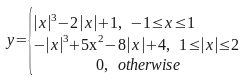 | 220% |
Lanczos | 6 | 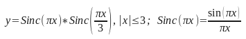 | 380% |
Hamming | 6 | 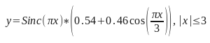 | 360% |
Blackman | 6 | 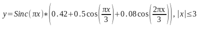 | 400% |
To show the effect of using various filters more clearly, we apply resampling (i.e. Change Density) operation to the same raster image with different filters activated.
Source image for further comparisons has been obtained from some original image scanned at density 300 dpi, by resampling it down to 100 dpi. Then the 100-dpi picture has been resampled back to 300 dpi, using various filters. With such procedure, we may compare effects of applying various filters to actual source image, with original image treated as ideal reference and practically unreachable target.
Figure 1 presents both images.
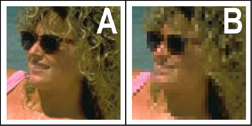
A - original image scanned at 300 dpi;
B – the same image resampled to 100 dpi and used as source for comparisons.
Figure 2 presents effects of resampling 100-dpi source picture B up to 300 dpi trying to reconstruct original picture A, with successive filters used.
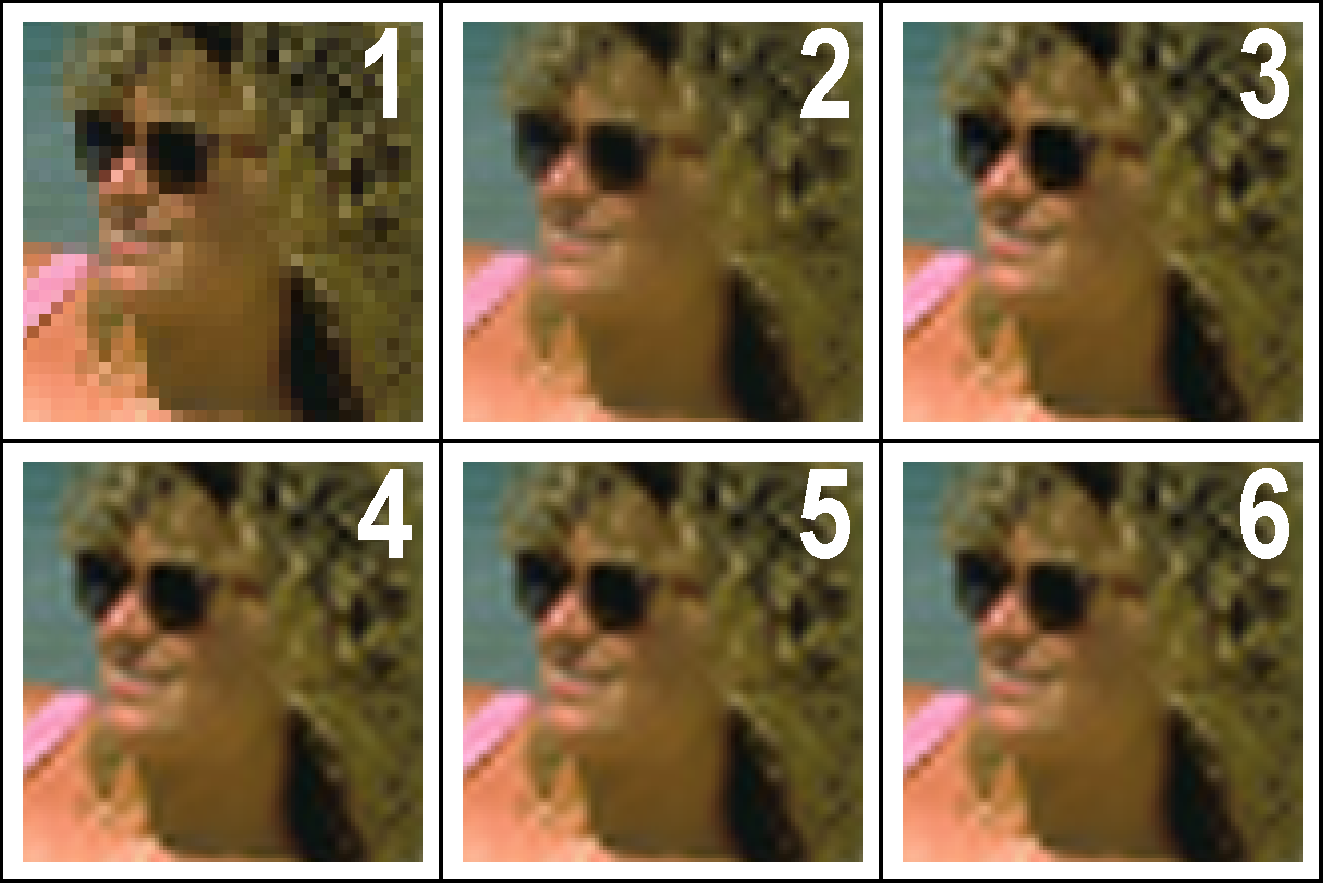
Box filter;
Linear filter;
Cubic filter;
Lanczos filter;
Hamming filter;
Blackman filter.
We may observe that:
the Box filter does not improve source image at all, simply replicating source pixels;
the Linear filter performs simplest interpolation, but with excessive blurring;
the Cubic filter gives better sharpness, but at cost of excessive ringing (see bright effect on the left from dark eye-glasses);
the Lanczos and Hamming filter give better results, with more balanced blurring and ringing effects;
the Blackman filter seems to be the best one, but is computationally most sophisticated.
Although precise choice of filter type may be individual for each type of image, the general decision when to use filter and when to not filter at all (i.e. use box filter, which is implemented as fastest method of processing) may be taken basing on image color format.
Monochrome drawings are not suitable for filtering at all, since they have no intermediate shades between black and white.
Palette drawings with 16-colors palette often have cartoon-like shapes with distinct colors; using filtering may result in false lines of intermediate colors between these shapes (e.g. magenta line between blue and red shapes).
Palette drawings with 256-colors palette are generally more suitable for filtering. However, this kind of images sometimes result from originals containing greater number of colors and then dithered as in press-like photographs. Using filters while transforming that kind of images may not necessarily improve image quality.
Filtering is most suitable for so called true-color drawings, i.e. images with 16 million colors (stored as 24 bits per pixel, with 8 bits per each basic color). However, you may want to disable filtering even for these images in order to decrease processing time.
Option In any color format enables filtering always when transforming color and gray-scaled images.
Option Above 16 colors enables filtering for color and gray-scaled 256-palette images as well as for true-color images.
Option In true-color only limits filtering only to true-color images.
Option Do not use disables filtering at all.
The default setting is Above 16 colors.
When the palette image is to be transformed using filtering, it requires converting to true-color format for processing and converting result back while storing. Rounding 8 bits per each basic color to some lower value, e.g. 7, 6, 5 or 4 bits may shorten converting and processing time, with slight degradation of color precision.
Successive options named 4 bits per color, 5 bits per color, 6 bits per color and 7 bits per color declare which rounding is to be used.
The default setting is rounding to 6 bits per each basic color.
New raster editing library enhances use of fill color and image transparency concepts, used in advanced image processing applications.
The fill color defined from the Fill Color Filter dialog is involved in several situations.
In Clear Rectangles / Polygons operations, the fill color fills the area defined for clearing.
Similar “clearing to fill color” is done during Cut Rectangle / Polygon operations.
In Crop Rectangle / Polygon operations, the fill color is used to paint redefined parts of raster image.
Similar “completing by fill color” is done during Cut / Copy Rectangle / Polygon, regarding exported part of image.
In Rotate / Calibrate Drawing operations, the fill color is used to paint undefined parts of raster image, that complete transformed shape of original image to the extent of new image.
In Paste Drawing operation, the fill color similarly completes redefined image extent if the pasted drawing exceeds it.
However, the most important use of fill color during pasting is its interpretation in image being pasted.
All parts of this image that have the same color as the fill color are treated as if they were transparent.
It enables to handle properly such situations as pasting complicated raster shapes obtained in Cut / Copy Polygon operation, even after resizing and rotating pasted drawing.
The default fill color is white. You may have to redefine it to some other color that is not involved in Cut / Copy / Paste operations, to obtain proper results.
The set of transparent colors defined from the Transparent Color Filter dialog enables to define and modify selective transparent areas using
Transparent Clear Rectangles / Polygons and Transparent Mask – Invert / Remove operations.
Transparent masks introduced in color drawing are now transformed properly in Resize / Rotate / Calibrate operations and preserved in Cut / Copy / Paste operations.
In Paste Drawing operation, interpretation of image transparency in drawing being pasted depends on the setting of
Enable image transparency option from the View tab on Configuration dialog.
Those areas of pasted drawing that have been defined as transparent ones, are not pasted to current drawing if the Enable image transparency option is on.
Otherwise, the whole drawing (excluding areas of color equal to fill color – see previous section) is pasted, ignoring transparent mask.
