
All CADRaster commands are available from the keyboard, from the CADRaster toolbar and from the CADRaster ribbon (ribbon since CADRaster 2012).
Under AutoCAD LT97-2007 CADRaster commands are available only from toolbar.
All keyboard commands begin with R, as in Raster.
The following CADRaster commands may be used transparently:
RNEW, ROPEN, RCLOSE, RSAVE, RSAVEAS, RDOC, RCONVERT, RSPLIT, RZOOM, RSELECT, RVIEW, RUNDO, RREDO, RREGEN, ROFF, RON, RSUSPEND, RCFG, RHELP, RABOUT
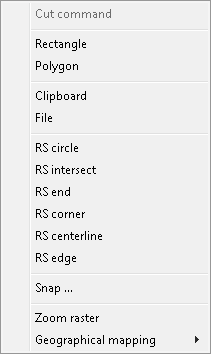
Most of CADRaster commands may be flavored in various ways by choosing one or more options from their Options and Tools Menu (OTM).
When a command is called for the first time, its OTM pops up automatically,
so that the user must choose the necessary options, e.g. for the Cut command you must choose either
Rectangle or Polygon and either Clipboard or File, as shown below:
When the same CADRaster command is called next time,
it assumes that the previously chosen options should be used, so that you don’t need to repeat the same clicking again.
When any change is needed, you may simply use the OTM hotkey (default: Ctrl+RightClick) immediately after clicking the command’s button on the toolbar and choose new options for the command.
Besides command options OTM provides convenient access to various tools, like command parameters, transparent raster snaps (RS) and the Zoom raster command.
You can redefine OTM hotkey using RCfg command (see Other tab description).
Note
Compatibility note
LTX: the following commands and options are not available:
RINSERT, RCALIB, RTRACE, RCUT, RCOPY, RPASTE, RSPLIT,
Merge printout colors, displaying geographical coordinates, editing transparent areas using RClear command.
LTX version allows editing monochrome raster images only.
PRO: all described above commands are available.
The RMenu command switches visibility of the CADRaster toolbar. You can drag it by its title bar to a convenient position on the screen.
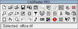
The first row buttons activate the following commands:
RNEW, ROPEN, RCLOSE, RSAVE, RSAVEAS, RDOC, RDWG2TCD, RCONVERT, RSPLIT, RSCANONE, RVPORTS, RTRACE, RCALIB
The second row buttons activate the following commands:
RMOVE, RCLEAR, RROTATE, RMATCH, RPAGE, RFILTER, RMERGE, RCREATE, RINSERT, RCUT, RCOPY, RPASTE
The third row buttons activate the following commands:
RZOOM, RSELECT, RVIEWS, RUNDO, RREDO, RREGEN, RON/ROFF, RCOLORS, RSUSPEND, RCFG, RHELP, RABOUT
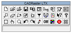
The first row buttons activate the following commands:
RNEW, ROPEN, RCLOSE, RSAVE, RSAVEAS, RDOC, RDWG2TCD, RCONVERT, RSCANONE, RVPORTS
The second row buttons activate the following commands:
RMOVE, RCLEAR, RROTATE, RMATCH, RPAGE, RFILTER, RMERGE, RCREATE, RHELP, RABOUT
The third row buttons activate the following commands:
RZOOM, RSELECT, RVIEWS, RUNDO, RREDO, RREGEN, RON/ROFF, RCOLORS, RSUSPEND, RCFG
The RNew command  is used to create a new empty composite document.
Subdocuments (raster and optionally vector drawings) can be added to such a document using the Composite Document dialog activated by the
is used to create a new empty composite document.
Subdocuments (raster and optionally vector drawings) can be added to such a document using the Composite Document dialog activated by the RDoc command.
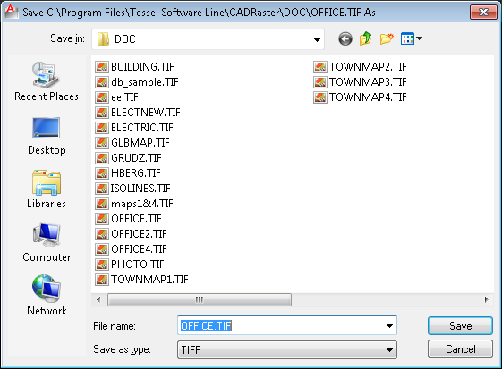
The ROpen command  is used for selection of a composite document or a single image file to be opened by CADRaster.
In the dialog box launched by the
is used for selection of a composite document or a single image file to be opened by CADRaster.
In the dialog box launched by the ROpen command you can select a needed file format type, disk drive and directory on this drive.
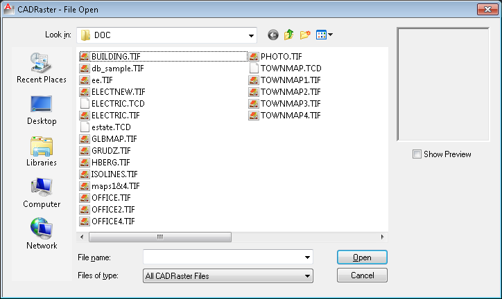
As a result of these selections the program will display the list of all files in the selected directory that have the chosen extension.
Every change of the format type, disk or directory is immediately reflected in the displayed list of files.
Opening of a document file from that list is done by selecting the file name with the left mouse button click and then clicking the Open (OK) button;
the left mouse button double click on the file name on the list is an alternative method.
When you select a Composite Document for opening and the Open foreground drawing automatically option is on,
CADRaster checks for a foreground drawing reference in the composite document and, if there is one, calls AutoCAD to open the foreground drawing.
See the description of RDoc command for more information on foreground drawings in CADRaster.
When you select a raster image or vector drawing file for opening,
CADRaster creates a new composite document that contains a reference to the single drawing just opened.
The configuration option Support Single Image Mode allows you to operate on a single image without creating a new TCD file (see the section called “RCfg”).
If this option is checked then file commands (RClose, RSave, RSaveAs) operate directly on an image file and the RDoc command displays a subdocument properties dialog instead of the Composite Document dialog.
The Single Image Mode described above facilitates viewing and editing of single raster and vector files without creating trivial composite documents that refer to one file only.
ROpenex is an extended version of the ROpen command.
It allows to open a raster image file with a name specified in the command line. Use one of the following syntaxes according to your needs:
AutoCAD command prompt example:
ROPENEX&C:\CADRPRO\DOC\electric.tif
AutoCAD script line example:
ROPENEX&C:\CADRPRO\DOC\electric.tif
AutoLISP example:
setq filename "C:\\CADRPRO\\DOC\\electric.tif"
command (strcat "ROPENEX&" filename)
The RClose command  terminates displaying of the currently opened composite document by closing the file with its contents.
When in the course of the CADRaster session the document has been modified, the user is asked to decide whether to save the changes.
terminates displaying of the currently opened composite document by closing the file with its contents.
When in the course of the CADRaster session the document has been modified, the user is asked to decide whether to save the changes.
If positive, the document will be saved in the same file from which it has been loaded (opened). The save operation will be performed on all subdocuments that have been modified in the session. If any of subdocuments before opening did not have TAF file, the user is asked for saving as well, in order that TAF file could be created.
The RSave command  saves the changes made to the current composite document in the same file from which the document has been loaded (opened).
At the same time changes made to all subdocuments are also saved, i.e. written to their respective files and their associated TAF files.
TAF files are created, if they did not existed before.
In Single Image Mode the changes are saved to the currently opened image file without saving the temporary TCD document and views (see the description of
saves the changes made to the current composite document in the same file from which the document has been loaded (opened).
At the same time changes made to all subdocuments are also saved, i.e. written to their respective files and their associated TAF files.
TAF files are created, if they did not existed before.
In Single Image Mode the changes are saved to the currently opened image file without saving the temporary TCD document and views (see the description of RViews command) are saved in the file with TCV extension.
The RSaveAs command  saves the current contents of the TCD document in a file different from which that document has been loaded.
In the dialog box invoked by this command select a disk drive and a directory on this drive.
Then enter, or select from the displayed list, a file name with TCD extension.
saves the current contents of the TCD document in a file different from which that document has been loaded.
In the dialog box invoked by this command select a disk drive and a directory on this drive.
Then enter, or select from the displayed list, a file name with TCD extension.
The RSaveAs command also saves the current contents of all subdocuments,
in a way that depends on the configuration option Copy subdocs while SavingAs...
TCD file (see the RCfg command). When the Copy subdocs... option is checked, the RSaveAs command automatically executes the Save as... command for each subdocument,
giving the user a possibility of creating new separate copies of subdocuments that belong to the newly created composite document.
When the Copy subdocs... option is not checked, the RSaveAs command automatically executes the Save command for each subdocument that has been modified during the session.
The newly created composite document will be linked to the same subdocument files as its ancestor.
In Single Image Mode the RSaveAs command saves the contents of the currently opened image in a different file of the same format.
If the file with the entered name exists, the program launches additional dialog box that asks you if you want to overwrite the existing file.
The rules of creating TAF and TCV files by RSaveAs command are the same as those concerning the RSave command (see the description of RSave command).
The RDoc command  launches the Composite Document dialog.
This dialog box groups together commands for composite document management on the subdocument level.
launches the Composite Document dialog.
This dialog box groups together commands for composite document management on the subdocument level.
All command buttons located on the right side of the Subdocuments list apply to one or more subdocument files that are highlighted at the moment. Using this commands it is possible to:
change properties of individual images (like their position or color);
enable/disable displaying of images;
select and unselect images for editing;
change the order in which they overlap each other;
add/delete images to/from the composite document;
change linking path to image files;
use relative or absolute image path name;
save changes made to subdocuments;
save subdocuments under new names;
copy subdocuments to new files.
The Common Extents of the current composite document are displayed below the Subdocuments list, together with two additional controls that let you do the following:
change the Units of the composite document (composite document extents are expressed in these units),
close the Composite Document dialog and apply the changes to the graphical screen.
The Composite Document dialog box displays a list of subdocuments that are linked to the current composite document. You can highlight the entries on this list in order to choose subdocuments for commands to operate on.
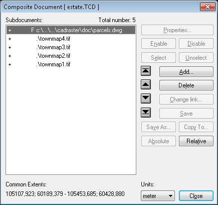
The Composite Document dialog box lists path names to subdocuments’ files preceded by four (4) status columns.
The first column contains plus sign (+), if the corresponding subdocument is enabled (visible) or minus sign (-), if the subdocument is disabled (invisible).
The second column may be empty or it may contain either the N/A text, if the subdocument’s file can not be found, or the R/O text, if the subdocument is open in the read-only mode.
The third column contains the S character, if the corresponding subdocument is in the selected state.
The names of selected subdocuments are printed in a different color in the listbox.
The fourth column contains the F character for foreground DWG subdocuments.
Additionally, a foreground subdocuments file name is displayed in gray color on the list.
There can only one foreground subdocument in each Composite Document.
CADRaster never opens Foreground subdocuments.
It calls AutoCAD to open them automatically, when Composite Document is opened and the Open foreground drawing automatically option (available through the RCfg command) is on.
Other Tessel Software Line applications may, however, open and edit foreground subdocuments.
In CADRaster the only way to add a foreground subdocument to Composite Document is by using the RDWG2TCD command.
For each subdocument its visible area, called viewport, is defined. Initially, right after adding a image to the composite document, the image’s viewport is set to its full extents.
Viewport extents can be changed using the RSelect command. The RResetVp command sets the viewports of currently selected images to their initial size (full extents of each respective image).
For each subdocument there is a possibility to change the displayed name of subdocument. To enter rename mode, select document name and press F2 button or click once more at the selected name.
CADRaster’s editing commands (RMove, RClear, etc.) operate only on subdocuments that are selected.
Subdocuments may be selected using either the Select and Unselect buttons in the Composite Document dialog,
or using the RSelect command from the keyboard or CADRaster toolbar.
The following sections describe commands (buttons) available from the Composite Document dialog.
The Properties... command is active only when exactly one subdocument is highlighted on the Subdocuments list.
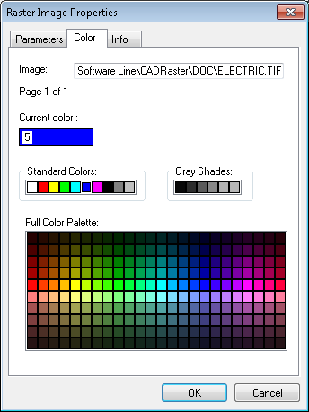
This command launches the Raster Image Properties dialog (or Vector Drawing Properties, depending on the current subdocument type)
for viewing and changing various properties and parameters of the highlighted subdocument.
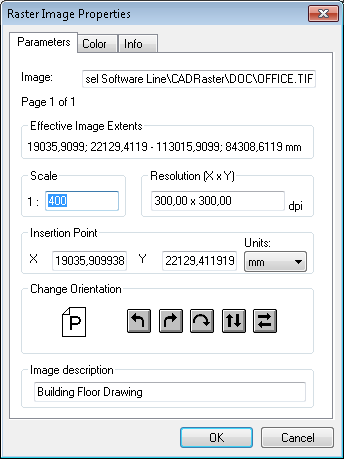
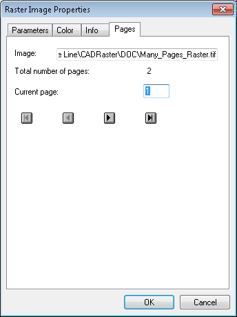
The Raster Image Properties dialog can have one, two or three tabbed pages. The page titled Parameters is always present. The page titled Pages is present only when the current raster image has multiple pages. The page titled Colors is present only when at least one image page is monochrome, so that it may have a presentation color assigned.
The Parameters page presents the following parameters that, except for the Extents, have been read from the image file header, its attributes file (TAF), or defined by the user using this dialog:
Effective Image Extents - calculated according to other parameters set for this raster image;
Scale - the nominal scale;
Resolution X x Y - the nominal horizontal and vertical resolutions of the bitmap in dots per inch;
Insertion Point - the insertion point coordinates, i.e. world coordinates of the bottom left corner of the image;
Units - units for the Insertion Point and Extents presentation;
Change orientation - buttons to rotate the view of the image left, right, by 180 degrees or perform vertical or horizontal mirroring of the view;
Image Description - optional description text.
On the Pages page you can select the current page of the multi-page raster image.
On the Colors page you can select a presentation color for monochrome raster image.
The values of image parameters are saved in the image file, if the image format allows for it,
and in an additional attribute file with the same name as the image file name but with TAF extension (see the section called “Appendices” for description of the TAF file format).
The additional file is located in the same disk directory as the image file.
The additional attribute file is necessary, because not every parameter can be saved in the original image file.
Parameters saved in the image file override parameters saved in its additional attribute file (TAF).
The creation and reading of attribute files can be controlled using the Parameters File Options located on the Configuration dialog (see the section called “RCfg”).
The Enable command turns visible all subdocuments that are highlighted on the Subdocuments list.
The visibility may be also affected by the drawing’s position on the Subdocuments list (see the Subdocuments order section below).
The Disable command turns invisible all subdocuments that are highlighted on the Subdocuments list.
The Select command changes to selected the state of all highlighted subdocuments on the Subdocuments list.
The S character appears before the name of each selected subdocument that is additionally displayed in a different color.
This method of selecting is alternative to the cursor pointing method described in the RSelect command section below.
The Unselect command clears the selected state of all highlighted subdocuments on the Subdocuments list.
The S character before the name of each selected subdocument disappears and the color of its line is changed to the standard one.
This method of unselecting is alternative to the cursor pointing method described in the RSelect command section below.
The following four commands (buttons) allow to control the order in which the subdocuments overlap one another, when the composite document is displayed or printed. Each of them moves the highlighted subdocuments entries on the composite document’s Subdocuments list.
The Bring to front command  moves the highlighted subdocuments to the front end of the Subdocuments list, i.e. makes them cover the other drawings.
The Bring forward command  moves the highlighted subdocuments one step in the front direction on the Subdocuments list, i.e. makes them cover the drawing which immediately preceded them.
Issuing the Bring forward command sufficient number of times is equivalent to issuing the Bring to front command one time.
moves the highlighted subdocuments one step in the front direction on the Subdocuments list, i.e. makes them cover the drawing which immediately preceded them.
Issuing the Bring forward command sufficient number of times is equivalent to issuing the Bring to front command one time.
The Send backward command  moves the highlighted subdocuments one step in the back direction on the Subdocuments list , i.e. puts them under the drawing which immediately followed them.
Issuing the
moves the highlighted subdocuments one step in the back direction on the Subdocuments list , i.e. puts them under the drawing which immediately followed them.
Issuing the Send backward command sufficient number of times is equivalent to issuing the Send to back command one time.

The Add... command adds a new subdocument to the current composite document. It launches a dialog box for selection of a drawing file to be added.
The Delete command removes links to currently highlighted subdocuments from the composite document. Of course, it does not delete the drawings files.
The Change Link... command is used to define a new path to the subdocument that is highlighted on the Subdocuments list.
It is especially useful when the previous files location is not valid (indicated by N/A on the Subdocuments list), e.g. after moving it to another directory.
The Change Link... command can be issued only when exactly one subdocument is highlighted on the Subdocuments list.
The Save command is active only when exactly one subdocument is highlighted on the Subdocuments list and if there are any unsaved changes made to its contents or parameters.
This command saves the changes to the highlighted drawing file and/or to its associated attribute file.
It operates only on the highlighted subdocument and does not save changes made to other subdocuments or to the whole
composite document that should be saved using the RSave command (or the Save button on the CADRaster toolbar).
The Save As... command is active only when exactly one subdocument is highlighted on the Subdocuments list.
It copies the highlighted drawing file (with its associated attributes file (TAF), if one exists) to the location specified by the user in the Save As... dialog box.
The highlighted source subdocument file is left unchanged while all editing changes made to it are saved in the newly created copy.
The Save As... command updates the current composite document link to the highlighted drawing, so that it contains the path to the newly created copy.
The Copy To... command is active only when exactly one subdocument is highlighted on the Subdocuments list.
It copies the highlighted drawing file (with its associated attributes file (TAF), if one exists) to the location specified by the user in the Copy To... dialog box.
The highlighted source subdocument is left unchanged while all editing changes made to it are saved in the newly created copy.
The Copy To... command leaves the current composite document unchanged, i.e. linked to the original drawing file.
Subdocuments in current TCD document can be stored with path names relative to theirs owner location.
In the Composite Document dialog (RDoc command) there are two buttons: 'Absolute' and 'Relative'
that may be used to switch path names of documents currently selected in Subdocuments list to absolute or relative.
CADRaster interprets relative names according to current TCD file location.
Files in current TCD folder or its subfolders may be relative.
The feature simplifies Composite Documents handling, copying and moving to other folders or computers.
The RZoom command  displays the view of the whole
current TCD document so it fills up possibly largest part of the AutoCAD’s window.
If a foreground AutoCAD drawing (DWG) is opened at the same time, AutoCAD is made to zoom it accordingly, so that the proper registration between the foreground DWG drawing and the background composite document is maintained automatically.
displays the view of the whole
current TCD document so it fills up possibly largest part of the AutoCAD’s window.
If a foreground AutoCAD drawing (DWG) is opened at the same time, AutoCAD is made to zoom it accordingly, so that the proper registration between the foreground DWG drawing and the background composite document is maintained automatically.
All other kinds of zooming are performed using the standard AutoCAD ZOOM command with all its available options.
Also here CADRaster maintains, of course, the correct registration of DWG and composite document views.
The ROff command  temporarily disables displaying of the currently opened background composite document.
It is useful when the user wants to see, for a while, the AutoCAD foreground drawing (DWG) only.
The
temporarily disables displaying of the currently opened background composite document.
It is useful when the user wants to see, for a while, the AutoCAD foreground drawing (DWG) only.
The ROn command enables displaying of the background document again.
CADRaster performance is optimized for viewing large raster and vector documents.
For each open document it keeps in its view cache a full view of that document (if this option is enabled).
This feature allows to execute the RZoom command very fast.
In some situations, however, the use of the view cache can somewhat decrease the quality of the document display.
In this case the user can issue the RRegen command  which forces the full resolution redraw without using the stored view.
You can control storing and using of the view cache in the
which forces the full resolution redraw without using the stored view.
You can control storing and using of the view cache in the RCfg command.
Views manager, closely integrated with the TCD document, provides the means for fast previewing and defining named zoom views that are stored in the document (or in TCV files for single-file documents) for future reference. For each view the user may add additional remarks in the description field. Because the process of regeneration takes some time, storing prepared image bitmap in the TCD document may accelerate the viewing.
When CADRaster works in Single Image Mode, i.e. file operations are performed on a single image without TCD file, views’ definitions are stored in a ImageName.TCV file.
This additional file is automatically created by the Save command and used by CADRaster if found in the image’s directory.
Full view, representing the entire document, is created and stored by CADRaster automatically.
Additionally the user may define named views.
Both types of views may be selected as default to be shown on open.
The RViews command  opens a dialog that displays the list of named views and offers the choice of views-related operations.
Views may be selected by clicking their names.
Double-clicking on the name of the view on the list is equivalent to pressing the
opens a dialog that displays the list of named views and offers the choice of views-related operations.
Views may be selected by clicking their names.
Double-clicking on the name of the view on the list is equivalent to pressing the Show button for this view.
The default view is shown at the bottom of the dialog. Views-related operations are executed in response to pressing respective buttons.
The Views dialog remains on the screen until the Close button is pressed.
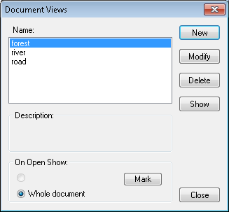
The following command buttons are offered in the Views dialog:
New - define new named view. You can give a name to the currently displayed part of document. World coordinates of the current zoom window will be stored as the view definition.
Modify - modify the parameters or name of the selected view. You may give a new name (it must be unique) for an existing view. You may also change this view definition by typing world coordinates into appropriate boxes.
Delete - delete the selected view(s). After deleting, the list of views is updated accordingly.
Show - show the selected view. After pressing this button, the view is shown in the AutoCAD’s drawing window. Pressing this button is equivalent to double-clicking on the name of the view on the list.
Mark - define the selected view as a default one. Only one default view is assigned to each TCD document. This view may be selected for showing when the document is initially opened.
The RConvert command  changes the format of raster data.
A dialog box named File(s) to Convert, otherwise identical to the dialog box in the
changes the format of raster data.
A dialog box named File(s) to Convert, otherwise identical to the dialog box in the ROpen command, is launched for selecting the files to be converted.
A similar dialog box Destination File(s) is used for selecting a new image format, file name and destination (disk drive and directory).
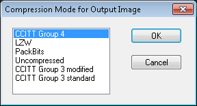
If the newly selected file format supports multiple compression modes, an additional dialog box appears for precise selection of a desired file subformat.
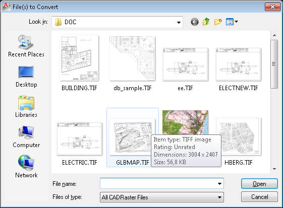
The list of output file formats and compression modes depends on the format of the converted (input) file. The full list of formats that are available in each case is displayed in the File Type list box.
When multiple input files are selected, they are converted to separate destination files with names taken from the input files and with the same common extension selected by the user for the whole group.
This may be changed by setting the ConvertToOneFile parameter in the cadrpro.ini file to 1 (see the section called “CADRPRO.INI file” for description),
so that a single destination file in one of multi-page formats (TIFF, DCX) will be created.
Each page in the resulting document will contain data from the corresponding input file.
When "RCFG/Edit/Convert to one file" option is disabled and user select multipage raster document then convert method create in destination directory 'N' one page only image files. 'N' is number of pages in source file.
Command RSplit  is available from CADRaster ribbon.
CADRaster editing commands can process single raster images not larger than 32000 pixels in both directions.
The RSplit command enables processing larger images by dividing them into smaller segments that are seamlessly linked to create a Tessel Composite Document (TCD) representing the entire source image.
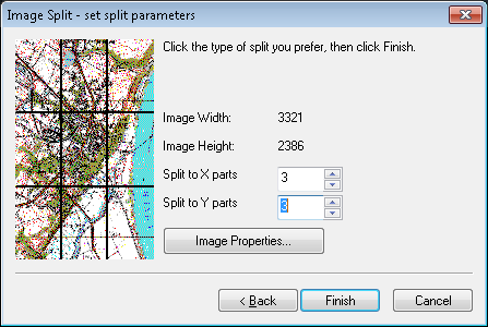
The RSplit command allows you selecting a source image file, choosing a name and destination directory for a new TCD file and defining the number of segments to divide the source image into.
Once the resulting TCD file is created, you may open it and perform usual editing operations on smaller images, selecting them independently or in groups.
This command can be activated by typing RSplit at command prompt or by pressing RConvert toolbar button while the Shift key is pressed.
The RImport command has been added to support conversion of AutoCAD raster image objects to CADRaster ones.
This command is used to import standard AutoCAD images from the opened DWG file to CADRaster, so they can be edited using CADRaster tools.
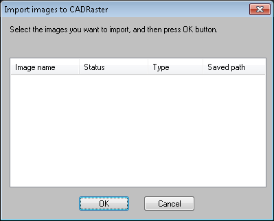
To import images type RImport at command prompt, than select images you want to import and press the OK button.
All selected images will be added to the currently opened (or newly created) TCD document. This command is available from keyboard under AutoCAD R14-2007 only.
This command will be performed automatically during loading DWG files, if the Import R14 raster images option is enabled on the Open page on the Configuration dialog.
The RImport command is automatically activated only if DWG file contains R14 references but does not contain any CADRaster image references yet, i.e. the image import process can be done automatically only once.
The RSelect command  is used to select graphically those subdocuments from the Subdocuments list that are to be affected by CADRaster editing commands.
Alternatively, the selection process may be done also in the Composite Document dialog by highlighting entries on the Subdocuments list and using the
is used to select graphically those subdocuments from the Subdocuments list that are to be affected by CADRaster editing commands.
Alternatively, the selection process may be done also in the Composite Document dialog by highlighting entries on the Subdocuments list and using the Select and Unselect buttons.
When no subdocument is selected all editing commands are disabled and their toolbar buttons grayed.
When the RSelect command is invoked it cancels all previous selections, if any, and displays the boundaries of the subdocuments’ viewports.
A subdocument may be simply selected by clicking the left mouse button anywhere within its area.
First the currently defined viewports are taken into account, but if there is no viewport at the mouse click point, the full image extents are considered.
Two keys, Ctrl and Shift, modify the action taken by the RSelect command, as described below.
The Ctrl key decides which subdocuments are affected by the selecting action, whenever they overlap each other at the click point.
When the Ctrl key is released, only the subdocument that is on top at the click point is affected by the action.
When the Ctrl key is pressed, the selecting action will affect all subdocuments that may be overlaying each other at the click point.
The Shift key decides which of two possible selection styles is used.
When the Shift key is released, the subdocuments affected by the click get selected and the remaining subdocuments get unselected.
Pressing the Shift key toggles the selection state of relevant subdocuments is from selected to unselected and vice versa.
The Shift key is most often used for selecting groups of subdocuments.
The groups of neighboring subdocuments may be affected by the above described selection actions by clicking and dragging the mouse, instead of simple clicking. If the mouse is dragged from left to right, those subdocuments that lie completely inside the entered window are affected. If the mouse is dragged from right to left, subdocuments with extents intersecting the entered window are affected.
For each subdocument its visible area, called viewport, is defined. Initially (after adding a drawing to the composite document) it is set to full drawing extents.
A viewport can be resized by selecting the relevant drawing and dragging small black rectangles (called trackers) that appear in the corners and in the middles of edges of the selected drawing’s viewport.
Under AutoCAD Rel. 14 use RVports command for viewports edition.
The RResetVp command resets the viewports of currently selected documents to their initial sizes (full extents of each respective drawing).
Note, that while doing the graphical selection you can transparently perform only those AutoCAD commands that do not require mouse input.
If you must let AutoCAD control the mouse while in a CADRaster command, temporarily suspend CADRaster mouse processing by pressing the Ctrl-S key or pressing the Suspend mouse input button on the toolbar.
Pressing the ESC key cancels this command and deselects all subdocuments.
Clicking the right mouse button accepts selections and ends the command.
While in the Single image mode, the RSelect command may be automatically executed, immediately after the ROpen command, to select the only subdocument for editing.
In order to enable this feature, check the option AutoSelect single file documents in the RCfg dialog.
        RMOVE - Move raster - press Ctrl+RightClick for options
        Base raster point: Specify a point
        Destination point <current>: Specify a point
        RMOVE <OK>/Cancel/Modify: Enter an option or press Enter
The RMove command  moves the viewport (i.e. visible area) of the image with it as well. This way the same area of the image remains visible.
Modify option allows you to change command parameters before execution.
Options: Rectangle or Polygon, Opaque or Transparent
Rectangle
RCLEAR - Clear raster rectangles - press Ctrl+RightClick for options
            Define rectangle to clear. First corner: Specify a point
            Second corner: Specify a point
            Define rectangle to clear. First corner: Specify a point or Enter
            RCLEAR <OK>/Cancel/Modify: Enter an option or press Enter
Polygon
RCLEAR - Clear raster polygons - press Ctrl+RightClick for options
                Define polygon to clear. First point: Specify a point
                Next point: Specify a point
                Next point: Specify a point or Enter
                Define polygon to clear. First point: Specify a point or Enter
                RCLEAR <OK>/Cancel/Modify: Enter an option or press Enter
The RClear command  is used to erase unwanted areas from raster images (Opaque option) or to perform operations on the transparency mask (Transparent option).
Editing operation on the transparency mask is allowed on True-Color TIFF images only. Opaque operations work on all images.
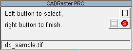
After issuing the RClear command, click the left mouse button to define vertices of the rectangle/polygon.
Click the right mouse button to finish defining vertices (the point of the right click is not included in the polygon definition).
is used to erase unwanted areas from raster images (Opaque option) or to perform operations on the transparency mask (Transparent option).
Editing operation on the transparency mask is allowed on True-Color TIFF images only. Opaque operations work on all images.
After issuing the RClear command, click the left mouse button to define vertices of the rectangle/polygon.
Click the right mouse button to finish defining vertices (the point of the right click is not included in the polygon definition).
After issuing the RClear command, click the left mouse button to define vertices of the rectangle/polygon.
Click the right mouse button to finish defining vertices (the point of the right click is not included in the polygon definition).
The RClear command working in Opaque mode erases unwanted areas from the raster image.
In monochrome images erased areas are filled by the background color.
For color images there is a need to specify which color should be used to fill the hole in the raster after a clear operation.
The intuitive white is not proper in most cases.
The user can define the best fill color using the RColors/Fill color command.
RCOLORS - Define color of raster fills - press Ctrl+RightClick for options
Sample point: Specify a point
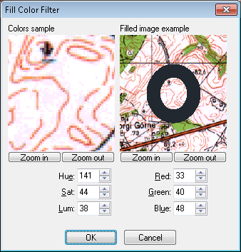
You define Fill Color using the RColors command with OTM Fill Color option.
First you pick a point on raster image where the color sample will be taken from.
You may use the transparent RSnap command to change the pickbox size, if you wish.
After clicking a point, the Fill Color dialog will appear on the screen.
The Colors sample window on the left side displays the chosen raster sample, while the Filled image example window on the right shows a view of the raster image around the pick point with a collar in selected color drawn on it. The collar is to help you to match raster image background with selected fill color.
You can modify Fill Color value (that consists of discrete color’s RGB values) by entering RGB or HSL parameters.
While performing editing operations on the transparent mask there is sometimes a need to specify which pixels should be made transparent.
By default all pixels in selected area are made transparent.
The RColors/Transparent colors command can be used to restrict RClear operations to pixels with color value between lower and upper range.
RCOLORS - Define transparent color of raster image- press Ctrl+RightClick for options
Sample point: Specify a point
You define Transparent Colors using the RColors command with the OTM Transparent Colors option.
First you pick a point on raster image where the color sample will be taken from.
You may use the transparent RSnap command to change the pickbox size, if you wish.
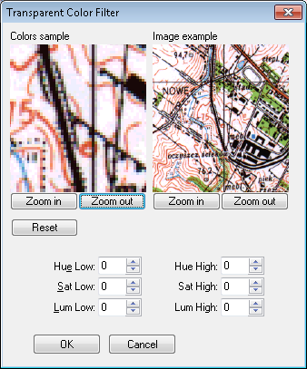
After clicking a point, the Transparent Colors Filter dialog will appear on the screen.
The Colors sample window on the left side displays the chosen raster sample, while the Image example window on the right shows a filtered view of the raster image around the pick point.
You can define Transparent Colors set (that consists of two color’s values, minimal and maximal) by clicking pixels in the Colors sample window or by entering color value from keyboard.
When you pick a new color, it is added to the color set and all image pixels with colors in the selected range are made transparent.
The ranges of colors currently in the set are shown at the bottom of the dialog. The Reset button restores default color set.
The default range of transparency mask includes all colors, so all pixels are set to transparent during RClear command.
You may select a different background color (available inside the dialog) to preview corresponding raster image on changed background.
RRotate command  options are:
Rotate, Align and Rotate by …
Rotate
RROTATE - Rotate raster - press Ctrl+RightClick for options
Base raster point: Specify a point
Rotation angle: Specify an angle or specify a point
RROTATE <OK>/Cancel/Modify: Enter an option or press Enter
Align
RROTATE - Align raster - press Ctrl+RightClick for options
First point of reference line: Specify a point
Second point of reference line: Specify a point
Second point of aligned line <Horizontal>/Vertical: Specify a point or enter an option
RROTATE <OK>/Cancel/Modify: Enter an option or press Enter
Rotate by …
RROTATE - Rotate raster - press Ctrl+RightClick for options
In CADRaster OTM menu following options will be available:
left by 90 degrees, left by 180 degrees, left by 270 degreess, flip horizontal, flip vertical
RROTATE <OK>/Cancel/Modify: Enter an option or press Enter
The rotation of raster images is one of the most important capabilities of CADRaster.
Using the RRotate command you can match the raster image and the vector drawing if the first one needs to be rotated.
The image rotation may be specified starting from any of the image orientation angles.
The RRotate function interactively supports the specification of a rotation angle.
The rotate operation modifies the raster image file according to the new image layout.
Functions RPage and RMove may then be used in order to place the rotated image in AutoCAD coordinates.
The alignment of raster images is similar to the rotation. The alignment function is controlled by a different interactive interface.
Using this function you can easily match any line of the background raster image to the foreground vector drawing. The alignment operation is done by rotation, independently of the standard orientation of the raster image.
The RRotate/Align function interactively supports specification of a new aligned position of the raster image.
You define base reference line and aligned line position.
Selected images are rotated in such a way, that the reference line is rotated to the position of the destination line.
RRotate command may be also used when multiple raster images are selected - all of them will be rotated around the same angle.
The RRotate By … function rotates the raster image by 90, 180 or 270 degrees, turns it upside down or makes a mirror image of it, depending on user's choice.
It performs physical rotation of raster data contrary to orientation change done by the RDoc command.
Options for RMatch command  :
:
Match or Resize
Match
RMATCH - Match raster - press Ctrl+RightClick for options
Raster point #1: Specify a point
Target point #1: Specify a point
Raster point #2: Specify a point
Target point #2: Specify a point
Raster point #3: Specify a point
Target point #3: Specify a point or press Enter
RMATCH <OK>/Cancel/Modify: Enter an option or press Enter
The Match option is used to easily match raster background to vector objects or specific world coordinates.
It uses CADRaster calibrator do perform one of 3 basic raster transformations: Helmert, Affine or bilinear.
The transformation parameters are defined easily by simple clicking of raster points and then picking target positions for them.
The function chooses appropriate calibration model automatically, depending on the number of specified matching vectors:
2 vectors
Helmert transformation, results in raster move, rotation and resizing equal in both X&Y directions.
3 vectors
Affine transformation, results in raster move, rotation and resizing independently in both X&Y directions.
more vectors
as above or bilinear transformation capable of compensating rhomboid distortions.
The bilinear transformation is chosen only if and OTM option Bilinear model is checked.
Use OTM hotkey (default: Ctrl-RightClick) to popup OTM menu and choose the option accordingly to the raster matching operation you need
Resize
RMATCH - Resize raster - press Ctrl+RightClick for options
Base raster point: Specify a point
Raster reference point or X scale factor: Specify a point
Destination point: Specify a point
X scale factor
Y scale factor
RMATCH <OK>/Cancel/Modify: Enter an option or press Enter
The Resize option is used to expand or shrink raster images independently in X & Y directions by scale factors.
First you enter a Base raster point of resizing.
This point will remain fixed at its original position.
Then, you define Raster reference point and drag it to its Destination point.
This defines X and Y scale factors that will be used to resize the entire image accordingly.
Instead of defining Raster reference point and destination point you can enter X and Y scale factors directly.
This command may be also used when multiple raster images are selected - all of them will be resized using the same values of vertical and horizontal factors.
Options for RPage command  :
:
Crop rectangle, Crop polygon or Page
Crop rectangle
RPAGE - Crop raster rectangle - press Ctrl+RightClick for options
Define rectangle to crop. First corner: Specify a point
Second corner: Specify a point
RPAGE <OK>/Cancel/Modify: Enter an option or press Enter
Crop polygon
RPAGE - Crop raster polygon - press Ctrl+RightClick for options
Define polygon to crop. First point: Specify a point
Next point: Specify a point
Next point: Specify a point or press Enter
RPAGE <OK>/Cancel/Modify: Enter an option or press Enter
Page
RPAGE - Define new page size - press Ctrl+RightClick for options
Left lower corner <0.0000,0.0000>: Specify a point
RPAGE <OK>/Cancel/Modify: Enter an option or press Enter
The Crop option accepts a rectangle or polygon as a parameter and clears the area outside of it.
This command crops raster image to the common part of image’s former extents and the given cropping rectangle/polygon.
It may be also used when multiple raster images are selected. Images not intersecting the cropping rectangle are not affected.
The Page option allows you to define new dimensions of the raster image using standard paper formats.
The OTM contains several page formats that can be used in this command.
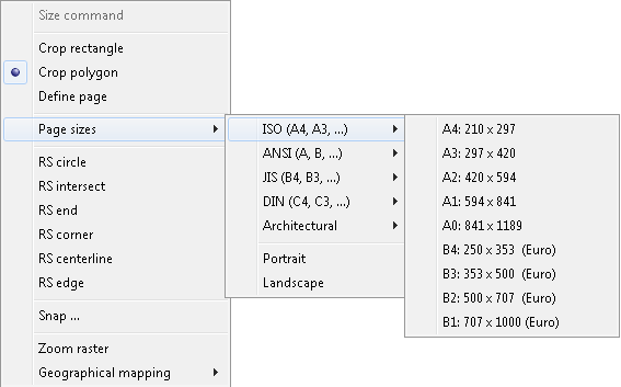
Size of the selected page is used to calculate requested page size in the world coordinates. Next, the user defines the location of raster image on the new page.
Optoins for RFilter command:  :
:
Filter spots, Filter holes or Change Density
Filter spots
RFILTER - Filter raster spots - press Ctrl+RightClick for options
Enter spots size in pixels, or
Use window to select a sample spot to remove: Specify a point or enter number
Second corner: Specify a point
Found size is 1822
Define rectangle to remove spots <whole image>: Specify a point or press Enter
Second corner: Specify a point
RFILTER <OK>/Cancel/Modify: Enter an option or press Enter
Filter holes
RFILTER - Filter raster holes - press Ctrl+RightClick for options
Enter holes size in pixels, or
Use window to select a sample spot to remove: Specify a point or enter number
Second corner: Specify a point
Found size is 22
Define rectangle to remove holes <whole image>: Specify a point or press Enter
Second corner: Specify a point
RFILTER <OK>/Cancel/Modify: Enter an option or press Enter
Change density
RFILTER - Change raster density - press Ctrl+RightClick for options
X resolution <300.0000>: Enter a value or press Enter
Y resolution <300.0000>: Enter a value or press Enter
RFILTER <OK>/Cancel/Modify: Enter an option or press Enter
Scanned drawings often contain small spots or holes (areas of connected pixels) as a result of bad quality of their paper originals. The Filter Spots or Filter Holes options allows you to remove spot or holes that contain less or equal pixels than defined by the user. You can define maximal spot/hole to remove by selecting sample spot/hole from the raster image or entering maximal spot/hole size from the keyboard. You can remove spots/holes from the whole raster image or defined rectangular area.
The Change Density option is used to change the resolution of raster image.
It changes the Resolution property of the raster image to a new value (independently for X & Y, if needed) and recalculates raster data accordingly, so that the resulting image extents do not change.
Raster pixels are glued together when decreasing resolution, or they are replicated when increasing it. This option is available only when one raster image is selected.
This command can edit monochrome images only.
Note
This option is available only in CADRaster PRO.
Options for RCut command  :
:
Rectangle, Polygon, File, Clipboard
Rectangle - Clipboard
RCUT - Cut raster rectangle to clipboard - press Ctrl+RightClick for options
Define rectangle to cut. First corner: Specify a point
Second corner: Specify a point
Insertion base point: Specify a point
RCUT <OK>/Cancel/Modify: Enter an option or press Enter
Polygon - File
RCUT - Cut raster polygon to file - press Ctrl+RightClick for options
Define polygon to cut. First point: Specify a point
Next point: Specify a point
Next point: Specify a point or Enter
Insertion base point: Specify a point
RCUT <OK>/Cancel/Modify: Enter an option or press Enter
You can cut a rectangular area or a free-shaped polygon.
The RCut command removes a specified raster data, defines its Insertion base point, and places it in the CADRaster Clipboard or in a separate raster file.
CADRaster Clipboard is a special temporary file created for single CADRaster’s session.
Subsequent RCut or RCopy commands overwrite contents of CADRaster Clipboard.
You can paste contents of CADRaster Clipboard to selected raster image.
This command is available only when one raster image is selected.
Options for RCopy command  :
:
Rectangle, Polygon, File, Clipboard
Rectangle - Clipboard
RCOPY - Copy raster rectangle to clipboard - press Ctrl+RightClick for options
Define rectangle to copy. First corner: Specify a point
Second corner: Specify a point
Insertion base point: Specify a point
RCOPY <OK>/Cancel/Modify: Enter an option or press Enter
RCOPY - Copy raster polygon to file - press Ctrl+RightClick for options
Define polygon to copy. First point: Specify a point
Next point: Specify a point
Next point: Specify a point or Enter
Insertion base point: Specify a point
RCOPY <OK>/Cancel/Modify: Enter an option or press Enter
You can copy a rectangular area or a free-shape polygon.
The RCopy command makes a copy of a specified raster data, defines its Base Insertion Point, and places it in the CADRaster Clipboard or in a separate raster file.
CADRaster Clipboard is a special temporary file created for single CADRaster’s session.
Subsequent RCut or RCopy commands overwrite contents of CADRaster Clipboard.
You can paste contents of CADRaster Clipboard to selected raster image.
This command is available only when one raster image is selected.
Note
This option is available only in CADRaster PRO.
Options for RPaste command  :
:
File, Clipboard
Important
If CADRaster Clipboard is empty, the command switches to File mode automatically.
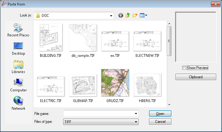
File
RPASTE - Paste raster from file - press Ctrl+RightClick for options
Clipboard / File
RPASTE - Paste raster from clipboard - press Ctrl+RightClick for options
Insertion point <current> Specify a point
X scale factor <current>: Specify a scale or press Enter
Y scale factor <current>: Enter a scale value or press Enter
Rotation angle: Specify an angle or press Enter
RPASTE <OK>/Cancel/Modify: Enter an option or press Enter
You can paste the contents of the CADRaster Clipboard or a raster image from a named file.
The RPaste command inserts a copy of the selected file contents at the specified position of the insertion point after having performed the required rescaling and rotation.
The image pasting is performed in world coordinates and all transformations that are necessary to compensate for differences in resolution, orientation, units and scale of source and target images are performed automatically.

Note
This option is available only in CADRaster PRO.
The RInsert command  inserts vector entities into the raster images.
The editing process starts from the specification of a rectangular area of the vector drawing on the background of the raster image.
CADRaster rasterizes the vector entities from the defined area.
Finally, the original raster data is merged with the new raster data with a resolution equal to the original file.
The command internally uses the standard PLOT command and requires plotter device based on CADRaster Printer Driver (see chapter 1.4.1 for plotter configuration instruction).
inserts vector entities into the raster images.
The editing process starts from the specification of a rectangular area of the vector drawing on the background of the raster image.
CADRaster rasterizes the vector entities from the defined area.
Finally, the original raster data is merged with the new raster data with a resolution equal to the original file.
The command internally uses the standard PLOT command and requires plotter device based on CADRaster Printer Driver (see chapter 1.4.1 for plotter configuration instruction).
RINSERT - Insert vectors to raster
Define rectangle to rasterize: First corner: Specify a point
Second corner: Specify a point
RINSERT <OK>/Cancel/Modify: Enter an option or press Enter
The RCreate command  creates a new raster image by rasterizing the current vector drawing or any part of it.
The command internally uses the standard PLOT command and then internal CADRaster's rasterization engine to produce an image of the requested size and resolution.
creates a new raster image by rasterizing the current vector drawing or any part of it.
The command internally uses the standard PLOT command and then internal CADRaster's rasterization engine to produce an image of the requested size and resolution.
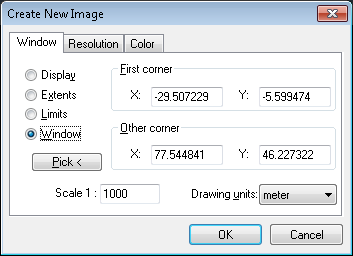
First, a dialog page Window is used to determine which rectangular area of the current drawing will be rasterized and at what scale. When you specify any rectangular area option, AutoCAD applies the rectangular area to the current viewport and the current space, whether it's model or paper space. A raster space plot includes all visible viewports and their contents. Viewports that have been turned off will not be rasterized. The MAXACTVP system variable is ignored. If a viewport is on and within the plottable paper space view, it will be plotted.
Display - plots the view in the current viewport
Extents - plots the portions of the current space of the drawing that contains object. This options is similar to ZOOM/Extents. If you plot extents with perspective view and the camera position is within the drawing extents, RCreate proceeds as though you have used the Display options.
Limits - plots the entire drawing area as defined by the drawing limits.
Window - plots any portions of the drawing. Click the Pick button and use the pointing device to designate the window if the area you want to specify is totally visible on the screen. You can also specify the window by entering the coordinates in the First Corner and Other Corner text boxes.
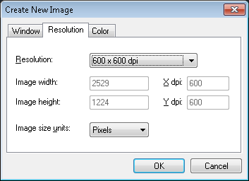
The Resolution page is used to specify created image resolution and to verify its size. To change resolution select first Resolution list box and then choose appropriate value. Choose Custom value if required resolution is not shown on this list. Then enter required value using X dpi or Y dpi edit field.
Calculated image width and height will be shown in inches, millimeters or in pixels.
Third dialog page Color is used to determine color type of the created image. You can choose between black and white, grayscale or some colors of different depth.
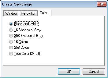
After pressing OK on RCreate dialog you select a raster file name, format and compression options for a file CADRaster will produce as a result of rasterization of AutoCAD’s vectors.
When RCreate is executed on AutoCAD 14 or LT97-2007 then new image file will contain currently displayed raster drawing.
If you want to create an image of vectors only, please turn off raster visibility using ROff command or close the raster drawing.
Note
This option is available only in CADRaster PRO.
Scanned drawings are often skewed, stretched, crumpled or damaged in some other way.
The RMatch command allows correction of the whole raster image based on simple calibration model or the comparison of vertical and horizontal distances between selected points.
This is not sufficient in more complicated situations when only a part of the raster image requires, sometimes non-linear, corrections.
Multi-point Calibration supports this kind of correction of deformed scanned images by applying a transformation computed according to one of five models:
Helmert, Affine, bilinear, biquadratic or bicubic.
Mathematically these models can be described as follows.
Isotropic linear (Helmert) model - requires at least 2 correction vectors.
x’ = a10 + a1 x + a2 y
        y’ = a20 - a2 x + as y
Anisotropic linear (Affine) model - requires at least 3 correction vectors.
x’ = a10 + a11 x + a12 y
y’ = a20 + a21 x + a22 y
Bilinear model, requires at least 4 correction vectors.
x’ = a10 + a11 x + a12 y + a13 xy
y’ = a20 + a21 x + a22 y + a23 xy
Biquadratic model, requires at least 9 correction vectors.
x’ = a10 + a11 x + a12 y + a13 xy + a14 x2 + a15 y2 +
a16 x2y + a17 xy2 + a18 x2y2
y’ = a20 + a21 x + a22 y + a23 xy + a24 x2 + a25 y2 +
a26 x2y + a27 xy2 + a28 x2y2
Bicubic model, requires at least 16 correction vectors.
x’ = a10 + a11 x + a12 y + a13 xy + a14 x2 + a15 y2 +
a16 x2y + a17 xy2 + a18x2y2+a19 x3 + a20 x3y +
     a21 x3y2 + a22 x3y3 + a23 x2y3 + a24 xy3 + a25 y3
y’ = a30 + a31 x + a32 y + a33 xy + a34 x2 + a35 y2 +
a36 x2y + a37 xy2 + a38 x2y2 + a39 x3 + a40 x3y +
     a41 x3y2 + a42 x3y3 + a43 x2y3 + a44 xy3 + a45 y3
The aij parameters in each model are computed from the least mean squares formula, based on data provided by correction vectors. Each correction vector starts from the actual point (xno, yno) of the raster and ends in its desired position (xn*, yn*). The evaluated calibration function generates actual raster modification vectors that try to approximate the corrections imposed by user within the limits imposed by the chosen calibration model. They are shown as calculated vectors, each of which starts from the corresponding actual point (xno, yno) and ends in the model-computed corrected point (xn’, yn’).
The measure of accuracy may be achieved by comparing two mean square values: sqrt of mean-square correction (mean square length of correction vectors):
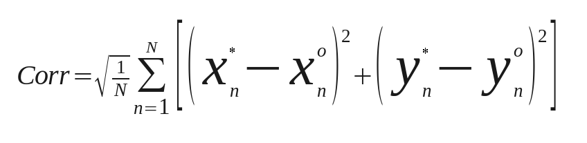
where N is the number of calibration data (correction vectors), and sqrt of mean-square error (mean-square difference between the requested and model-computed positions):
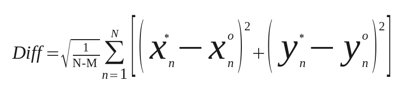
where M is the model order (the minimal number of vectors required to determine the model coefficients).
With M == N, the Diff is not computed because it has no statistical meaning, as the all requested points will be matched exactly.
Generally, the Diff should be small enough comparing to Corr.
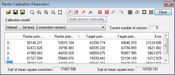
Calibration parameters are controlled by the Raster Calibration Parameters dialog.
This function  allows you to load calibration vectors from a file to which they were previously saved.
Practically, the calibration vectors may be re-used only if applied to exactly the same image they were defined for.
allows you to load calibration vectors from a file to which they were previously saved.
Practically, the calibration vectors may be re-used only if applied to exactly the same image they were defined for.
This function  allows you to save calibration vectors to a file for further usage.
The file format is ASCII. The file extension is
allows you to save calibration vectors to a file for further usage.
The file format is ASCII. The file extension is CAV.
This function  allows you to save calibration report in a file with the extension
 REP.
Calibration report contains calibration vectors definitions and actual position of vectors after calibration.
It contains also values of the requested mean-square correction and the remaining mean-square error (difference).
While the Raster Calibration Parameters dialog is on the screen, the CADRaster Toolbar is disabled.
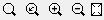
This zoom buttons give you an easy way to perform basic operations that concern current zoom level.
These operations are in order: Zoom window, Zoom previous, Zoom in, Zoom out and Zoom raster (RZoom).
This function  is used to define calibration vectors one by one manually.
First you enter a raster point to be corrected. It will become the starting point of a new correction vector.
Then you enter a target position for this point. It will become the ending point of the correction vector.
After entering these two points, the new correction vector is displayed as a Requested vector arrow (default red).
is used to define calibration vectors one by one manually.
First you enter a raster point to be corrected. It will become the starting point of a new correction vector.
Then you enter a target position for this point. It will become the ending point of the correction vector.
After entering these two points, the new correction vector is displayed as a Requested vector arrow (default red).
You may define any number of calibration vectors. The vectors can be previewed in the Calibration Vectors list box. If you click a vector in the list CADRaster zooms automatically to show the vector at the current AutoZoom level. The AutoZoom level may be changed using the Options dialog (see below). If you double-click on the vector in the list, CADRaster enters the vector editing mode allowing you to modify an existing correction vector.
This command  is used to define correction vectors one by one but with reference to pre-defined set of target points.
In the situation when a raster image needs to be calibrated to match, lets say, map coordinates grid, the functions automates the most standard activities,
like a zoom to next grid point, and provides precise definition of target points without typing their coordinates.
is used to define correction vectors one by one but with reference to pre-defined set of target points.
In the situation when a raster image needs to be calibrated to match, lets say, map coordinates grid, the functions automates the most standard activities,
like a zoom to next grid point, and provides precise definition of target points without typing their coordinates.
The net points defined using the Define base net command are used as Target points (ends) of correction vectors - the user needs only to select the corresponding
Raster points of correction vectors.
Moreover, automatic zooms are performed around the points in question, which maximizes the operator's speed.
The system zooms around the first point of the base net and you are asked to provide the corresponding raster point of the correction vector.
Here you may also choose one of the four OTM options: AutoZoom, Next Point, Previous Point, Skip defined.
The AutoZoom option allows choosing the level of zooming around the characteristic points of the calibration base.
The AutoZoom ratio (number of the raster image pixels per one screen pixel) can have one of 5 values:
Current, 2 to 1, 1 to 1, 1 to 2 and 1 to 4.
Instead of the AutoZoom option you can, of course, issue transparent ZOOM command and specify zoom for a given characteristic point, as it might be needed.
The Current option will keep next automatic zoom on the level used most recently.
The Next Point option allows you to skip defining the correction vector ending at the current characteristic point.
The Previous Point option moves you back to definition of previous point.
After using the Add net-based vectors command and skipping some vectors by Next Point, you may decide, that in fact you want to define them.
For that purpose you may use the Skip Defined option. You press the Add net-based vectors again and OTM Skip Defined takes you to the first characteristic point you have skipped and then to any other that is undefined.
You can stop defining the correction vectors using the calibration net base by pressing Esc.
This command  is analogous to adding net-based vectors but uses selected base entities as a source of target points for calibration vectors.
This command  switches CADRaster into mode of calibration vectors editing.
You are prompted to select a vector for editing and then you have a possibility to change its starting and ending points using grips.
The vector may be selected by clicking or by window.
switches CADRaster into mode of calibration vectors editing.
You are prompted to select a vector for editing and then you have a possibility to change its starting and ending points using grips.
The vector may be selected by clicking or by window.
After selecting a vector invoke OTM menu and select Edit option to start editing.
First click the grip you want to modify and next pick its new position.
You finish editing of the current vector by Esc or simple RightClick.
Another option of vector editing is Add that allows you to add manually new calibration vectors.
You can delete a correction vector using the Remove option. Clicking a vector in the listbox and pressing Del key may do the same.
Before calibration is performed the user may preview  its mathematical model to see whether it satisfies the requested corrections.
The preview displays requested (calibration) vectors in red and calculated vector in yellow.
The calibration area will be covered by a reference net that is transformed depending on calibration model into a calculated net.
The calculated net shows how the calibration process will modify the raster image.
its mathematical model to see whether it satisfies the requested corrections.
The preview displays requested (calibration) vectors in red and calculated vector in yellow.
The calibration area will be covered by a reference net that is transformed depending on calibration model into a calculated net.
The calculated net shows how the calibration process will modify the raster image.
The colors of preview elements may be changed using the Options function (see below)
If the preview is on, any changes to calibration model or calibration vectors are immediately shown in AutoCAD’s window.
After evaluating the transformation's coefficients and previewing it visually, you can apply the calibration using the Execute command
 .
The calibration report includes: date, time, the name of calibrated raster file, the calibration area, the name of calibration model used, the mean square length of requested correction vectors,
the mean square calibration error and the list of correction vectors.
Three points describe each correction vector in the calibration report: point to be corrected, its requested position and its position after calibration.
.
The calibration report includes: date, time, the name of calibrated raster file, the calibration area, the name of calibration model used, the mean square length of requested correction vectors,
the mean square calibration error and the list of correction vectors.
Three points describe each correction vector in the calibration report: point to be corrected, its requested position and its position after calibration.
It is possible to undo the calibration execution results using the Undo command 
Analogically you may redo  the previous undo effects.
This command  makes it easier to enter larger series of correction vectors.
When you calibrate an image, you often have a grid of points that should be placed in a regular way. In most cases these are crossing points of the coordinate system on a map that form a rectangular mesh.
The command launches the Calibration Net dialog where you may enter numbers of horizontal and vertical net vertices, single cell width and height and the net insertion point.
makes it easier to enter larger series of correction vectors.
When you calibrate an image, you often have a grid of points that should be placed in a regular way. In most cases these are crossing points of the coordinate system on a map that form a rectangular mesh.
The command launches the Calibration Net dialog where you may enter numbers of horizontal and vertical net vertices, single cell width and height and the net insertion point.
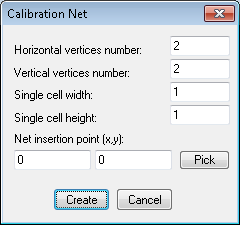
The net vertices supply target points’ coordinates to be used by the Add net-based vectors command.
The purpose of this command  is the same as Define base net but here you use any vector entity to define base points.
To use the command, you open a vector drawing or draw some vector objects (polylines, lines or points) that will serve as a source of target points coordinates.
The command prompts you to select relevant entities.
The points of selected vector entities supply target points’ coordinates to be used by the
is the same as Define base net but here you use any vector entity to define base points.
To use the command, you open a vector drawing or draw some vector objects (polylines, lines or points) that will serve as a source of target points coordinates.
The command prompts you to select relevant entities.
The points of selected vector entities supply target points’ coordinates to be used by the Add entities based vectors command.
The RCalib command  supports a multi-point calibration of a whole raster image or any rectangular part of its area.
The command pops up a calibration area definition dialog that allows you to define a window of raster image to be calibrated or select whole raster extents.
supports a multi-point calibration of a whole raster image or any rectangular part of its area.
The command pops up a calibration area definition dialog that allows you to define a window of raster image to be calibrated or select whole raster extents.

The RUndo command
is active only when there are some unsaved changes made to the current Tessel Composite Document.
The RUndo command cancels the changes made in the last step of editing.
If there are several unsaved steps of editing, the maximal number of available Undo steps is defined by the MaxUndoSteps parameter in the
cadrpro.ini file (see the section called “CADRPRO.INI file” for the description of cadrpro.ini file).
All changes made to image properties during each visit to the Composite Document dialog box are considered a single editing step.
To cancel all changes made to the composite document and its subdocuments, close it without saving and reopen the same document.
The RRedo command
is active only when there are some changes made to the current Tessel Composite Document that have been previously cancelled using the RUndo command.
The RRedo command brings those changes back. If the RUndo command has been issued several times, the RRedo command can be issued the same number of times, moving one step forward each time.
All changes made to image properties during each visit to the Composite Document dialog box are considered as a single editing step.
The RDWG2TCD command  adds the name of the DWG drawing opened currently by AutoCAD to the list of TCD subdocuments and marks it as foreground drawing.
When you subsequently open this Tessel Composite Document and the
adds the name of the DWG drawing opened currently by AutoCAD to the list of TCD subdocuments and marks it as foreground drawing.
When you subsequently open this Tessel Composite Document and the Open foreground drawing automatically option is on,
CADRaster finds the reference to a DWG foreground drawing and automatically calls AutoCAD to open it.
See the description of RDoc command for more information on foreground drawings in CADRaster.
This command is active only when a TCD file is open, so it may not be used when CADRaster operates in Single Image Mode.
The RResetVp command  resets the viewports of currently selected subdocuments to their initial sizes.
The initial size and location of each viewport matches the full extents of its respective drawing.
The above shown command button is available only inside the
resets the viewports of currently selected subdocuments to their initial sizes.
The initial size and location of each viewport matches the full extents of its respective drawing.
The above shown command button is available only inside the Selecting command.

CADRaster supports scanners with the TWAIN interface.
The scanning commands are available only if you have installed TWAIN-compatible software.
CADRaster checks if the TWAIN_32.DLL file exists in the Windows directory.
Use the RScanSource command to select a scanning device and the RScanPars command to set technical parameters of the scanning process.
You may also activate these commands using buttons from Other tab in the configuration dialog.
The RScanOne command starts scanning of a new single-page document.
The RScanMany command starts scanning of a new multiple page document that will be saved in a single image file.
You will be asked to select a file name and a raster format for the image that will be created as a result of scanning.
CADRaster creates a new composite document containing reference to this file, unless the Support Single Image Mode configuration option is checked.
The above commands are available only if you have properly installed TWAIN-compatible software.
The RScanOne command  starts scanning of a single-page document.
Depending on the type of the selected scanner it may be necessary to start the scanning physically, e.g. by pressing a button on the scanner. Some scanners can do it automatically, others can display their proprietary window with information about the scanning progress.
The RScanMany command starts scanning of a multiple-page document.
After each scanned page the dialog box informs you about the number of pages scanned so far. Four buttons are available (some of them can be disabled, depending on the situation):
Next- confirms the last scanned page and starts scanning of the next oneThe Same- repeats scanning of the last pageClose- confirms the last scanned page and stops scanning; the file will contain the number of pages as currently displayed in the dialog boxCancel- stops scanning and discards pages scanned so far.
Important
This command is available from the keyboard only.
The RScanSource command is used for selection of the current scanning device. This command is relevant only when more then one scanner is installed.
Click a scanner name and press the Select button to choose a scanning device.
Particular scanning parameters can be set using the RScanPars command.
The list shows only TWAIN-compatible devices that have been properly installed.
When the part of scanning software that is responsible for cooperation with applications that use the TWAIN standard is present,
the device should appear on the list of available scanners (no additional installation on the part of CADRaster is required).
The RScanPars command launches a dialog box that allows setting technical parameters of the scanning process.
This dialog box depends on the current scanner type and is displayed and managed by its driver.
The parameters are specific for the particular type of the scanner that is currently used.
After setting parameter values one must initialize the scanning process.
Note
Saving the parameter values is done during scanning. That is why, in order to save parameters, one must perform “dummy” scanning - it is not enough just to set the parameters up.
CADRaster provides the user with the set of tools for snapping to raster features and to trace raster lines both in monochrome and color images. The snap options may be used in any AutoCAD or CADRaster command transparently or you may set the continuous snapping mode, so that every mouse pick will be snapped to the currently chosen raster feature.
The RSnap command opens the Snap page of CADRaster configuration dialog. See the section called “RCfg” for more details.
Options for Filter color  are: Color fill, Filter color.
While snapping to selected features of color raster images CADRaster uses color filtering tool, called Color Range Mask, to pre-define the set of colors that belong to the objects being snapped to.
Filter color option
RCOLORS - Define snap/trace color filter - press Ctrl+RightClick for options
        Sample point: Specify a point
You define Color Range Mask using the RColors command with OTM Color Filter option.
First you pick a point on raster image where the color sample will be taken from.
You may use the transparent RSnap command to change the pickbox size, if you wish.
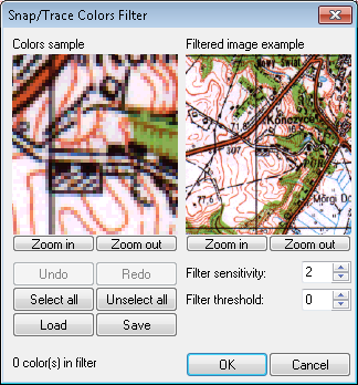
After clicking a point, the Snap Colors Filter dialog will appear on the screen.
The Colors sample window on the left side displays the chosen raster sample, while the Filtered image example window on the right shows a filtered view of the raster image around the pick point.
You define Color Range Mask (that consists of discrete color’s RGB values) by clicking pixels in the Colors sample window.
When you pick a new color, it is added to the mask and all its pixels are marked.
When you pick a previously selected color (marked pixel) it is removed from the mask.
You may also use the Undo/Redo and Select/Unselect all buttons to control this process.
The number of colors currently in the mask is shown at the bottom of the dialog.
The Filtered image example window shows only those parts of the raster image that will be ‘seen’ by the CADRaster’s snapping utility. You may click inside the window to display the corresponding B&W raster image instead of its color original.
The process of image filtering is additionally controlled by two parameters:
filter sensitivity
the range of this parameter is
0...255, default is preset to2;filter threshold
the range of this parameter is
-128...+128, default is preset to0.
You may try different values to check their influence on the image filtering results.
Color filter definitions may be saved and loaded from named files using the appropriate buttons.
RTrace  is a specialized tool for semiautomatic tracing of raster lines.
The command allows covering raster lines with vector polylines built of segments that are automatically fitted to raster lines curvature.
is a specialized tool for semiautomatic tracing of raster lines.
The command allows covering raster lines with vector polylines built of segments that are automatically fitted to raster lines curvature.
Note
This option is available only in CADRaster PRO.
After the command is started you have to click a point on raster line you want to trace.
The CADRaster tracer analyses raster background and returns a polyline segment that matches the pointed raster line.
The line stops at breaks and intersections, so if you want to continue tracing you must click the next segment.
CADRaster finds the next segment and connects its start point to an end point of the previous one.
At the end you get a single polyline covering the whole road you passed. Each segment after tracing has a direction, a property that is designed to help you following raster image lines.
CADRaster assumes that the start point of the segment is an end-point closer to the last user click.
Is you do not like the segment direction CADRaster assumed, you may change it with a Flip option.
There are several options that modify the behavior of this basic function. They may be accessed through OTM activated by OTM hotkey (default: Ctrl+RightClick).
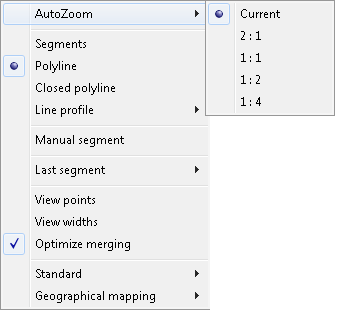
AutoZoom
when the trace goes through the raster line that finishes out of the screen, CADRaster performs an automatic zoom around the latest point allowing you to make a decision where to go with a next segment. The AutoZoom levels define a image pixels per one screen pixel. The Current option means: keep the current zoom level (for example after manual transparent zoom you made).
Segments
traced segment polylines will not be connected into one polyline.
Polyline
traced segment polylines will be connected into one polyline.
Closed polyline
traced segment polylines will be connected into one polyline that will be closed when the user accepts the
RTracecommand.
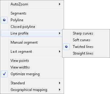
Line profile
the option defines what kind of lines will be traced, and sets tracer parameters accordingly (see the section called “RCfg”) to match raster line best. The preset values are for: straight lines, twisted lines, soft curves, sharp curves.
Manual segment
you may interrupt automatic tracing and enter a manually defined polyline where the tracer cannot vectorize some complicated parts of raster. The option starts typical polyline definition function. Further processing of manual segments is the same as for automatic ones.
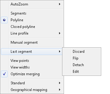
Last segment
you may perform some additional actions with the last traced segment:
discard - discard whole segment and start again from the last good point
flip - the last segment direction
edit - perform grips editing of the segment or add/remove vertex as well
break - finish the currently traced polyline with the previous segment and start a new polyline from the current segment.
View points
the grips of traced segments are shown in order to give you an orientation in tracing precision and possible errors
View widths
shows the traced line width that matches raster line width; this option does not work if the tracer option
Use raster line widthinRCfgcommand is not set.Optimize merging
if the option is set, the sequence of segments that form a single polyline is connected in such a way that end point of previous segment is connected to start point of next one. There is no double point in the place connecting segments.
The Configuration dialog contains the Tracer page where additional options controlling tracing are located (see the section called “RCfg”).
CADRaster’s raster snap commands may be also called transparently from the keyboard in order to perform single snap actions. The following commands are available:
'RCCR
Snap to center of circular raster shape
'RINT
Snap to intersection
'REND
Snap to line end
'RCOR
Snap to line corner
'RCEN
Snap to centerline
'REDG
Snap to area edge
Note
Please notice that, in contrast to AutoCAD , CADRaster’s transparent snap commands must be preceded by the ' sign.
The options are also available from OTM menu that may be activated by OTM hotkey (default: Ctrl+RightClick) both inside and outside of CADRaster commands.
The RCfg command  provides you with a tabbed dialog box for easy modification important configurable options of CADRaster.
The
provides you with a tabbed dialog box for easy modification important configurable options of CADRaster.
The RCfg command causes the changes to have an immediate effect for all commands in the current CADRaster session.
The same options are set in the cadrpro.ini file and may be changed manually there, but that way requires restarting of CADRaster.
Magnifying Glass tab
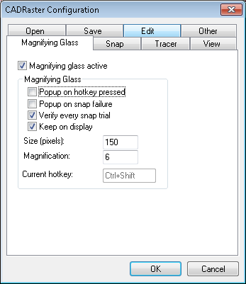
The Magnifying Glass tab allows you to configure the Magnifying Glass tool. Checking Magnifying Glass active box activates the function. When the Magnifying Glass window is displayed, you see a zoomed raster area around the position of the mouse pointer (the AutoCAD’s cross-hair) at the moment of the Magnifying Glass activation. If raster snap was active and successful, its result will be indicated by a cross symbol. If the snap result is not satisfactory, you may pick a new point precisely. The Keep on display option controls the method of closing the Magnifying Glass window. If option is not selected the Magnifying Glass window is closed automatically if you move the mouse cursor outside the window or you pick a new point inside the window. Otherwise the Magnifying Glass window disappears after pressing the Esc key or right mouse click. The Esc key cancels the point in the Magnifying Glass window. The right mouse click accepts the point and passes its coordinates to AutoCAD or CADRaster command, whichever was active at the time.
There are several methods of using the Magnifying Glass:
Popup on hot key pressed
Magnifying Glass window will be displayed after pressing the configured hot key
Popup on snap failure
Magnifying Glass window will be displayed if you tried to snap to raster and no snap point was found; this option is very useful with bad quality raster images that have jagged lines, many gaps, etc., that cause frequent raster snap failures
Verify every snap trial
Magnifying Glass window will be displayed after every raster snap trial, both unsuccessful and successful, to verify and/or correct its result
Keep on display
Magnifying Glass window will be closed after pressing the Esc key, which cancels the point, or right mouse click that accepts the point.
Other parameters on the Magnifying Glass tab allows the user to customize the Magnifying Glass window size in pixels and the magnification scale of raster. Current hot key may be changed simply by deleting it from its box and pressing a new key (or combination).
Snap tab
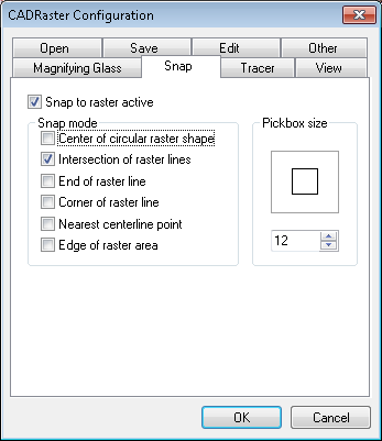
The Snap tab allows you to configure the Raster snap feature.
If the Snap to raster active option is checked, CADRaster is put into continuous snap mode.
Every click in the AutoCAD window is passed to CADRaster that searches for the best possible raster point that matches specified snap modes.
The function works similarly to AutoCAD’s OSNAP. You may snap to the nearest point on the centerline, end of raster line, intersection of raster lines, corner of raster line, to edge of raster area or to the center of small circular raster shape.
Raster Snap modes may be selected (and combined, if necessary) by checking their boxes in the dialog.
When multiple Snap modes are selected, CADRaster attempts to detect the relevant features of raster images according to the following hierarchy that corresponds to the order of the snap modes options shown in the dialog:
RCCR, RINT, REND, RCOR, RCEN, REDG.
If, for example, both raster line corner and intersection are detected within the snap pickbox area, the point of intersection, that is higher in the hierarchy, will be returned.
Similarly to AutoCAD CADRaster activates a pickbox to show the area where to look for a snap point. Depending on raster image contents and zoom level the user should chose a convenient pickbox size.
Tracer tab
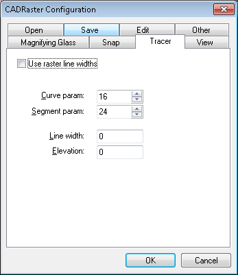
The Tracer tab allows you to configure line tracing parameters.
Use raster line widths
If checked, a traced polyline will have a width that matches the raster line width. If the option is not checked, the traced polyline width will be set to 0
Curve param
Available values are 1...32. The option says how precise to estimate raster line curvature. Smaller values give better precision.
Segment param
Available values are 1...32. The option defines minimal segment length in pixels. Smaller values allow for shorter minimal segments to be used for tracing.
Z coordinate
The option defines a value that is used as Z coordinate of polyline created by
RTracecommand. It allows you to place the newly created polyline on any depth level you want.Width of created polyline
This option specifies the constant width of new polyline created while tracing.
View tab
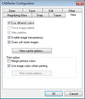
The View tab allows you to define view options:
Use dithered colors
If this option is checked CADRaster uses dithering to improve image colors mapping. The option is especially useful when displaying images with a lot of colors on display devices with only 16 or 256 physical colors. This option corresponds to the DitherMode parameter from the [TSLRVC Library Settings] section in the cadrpro.ini file.
Force image palette
AutoCAD uses a fixed palette of 256 colors that often do not match palettes of raster images. This may lead to incorrect display of color raster backgrounds. If the Force image palette option is checked CADRaster displays raster images using their own palette giving the best possible result on the screen. Unfortunately the vectors may be now displayed in wrong colors, so the option gives you a choice. The option does not affect printing that is done using original colors for both raster and vectors. This option corresponds to the ForceImagePalette parameter from the [CADRaster General] section in the cadrpro.ini file.
Alter palettes
The option corrects some problems with raster palette refreshing, however the effectiveness of that depends strongly on your Windows version, display driver type, display colors depth and AutoCAD’s ADI driver. If you will encounter strong problems with palettes management on your installation try switching the option off. It is likely that the older method of palette handling will be better for your specific installation.
Enable image transparency
This option is responsible for switching on or off the usage of transparency information defined in a raster image.
DRAW SOFT RASTER IMAGES
New "ClearView" technology enables displaying sharp and clear raster images, especially in large zoom-outs.
Merge printout colors
It is used to activate CADRaster function for transparent printing of vector entities (e.g. solids) on the raster background.
Use image colors when printing
If this option is checked CADRaster uses the original image colors while printing. If the option is not checked the images are printed as if they were black. This option corresponds to the
PrintColorsparameter from the [TSLPPL Library Settings] section in the cadrpro.ini file.
View and Print Cache Options
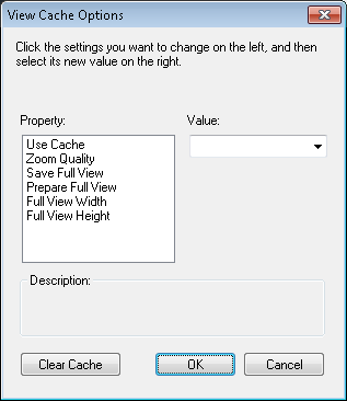
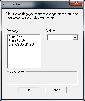
The View cache options or Print cache options buttons invoke configuration dialogs of CADRaster’s integrated view and print cache. All modified parameters are stored in the cadrpro.ini file. More information about modified property is specified in the section called “Appendices”.
Open tab
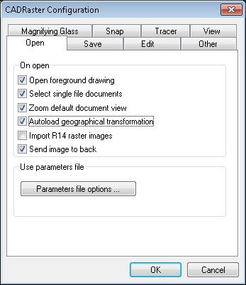
The Open tab allows you to configure options that control opening CADRaster files:
Open foreground drawing
If this option is checked and you open Tessel Composite Document containing a reference to a DWG foreground drawing, CADRaster calls AutoCAD to open that drawing. This option corresponds to the OpenForegroundDrawing parameter from the [TSLRVC Library Settings] section in the cadrpro.ini file.
Select single file documents
If this option is checked CADRaster automatically selects a single image file, or a TCD file with only one subdocument, immediately after the open operation. This option prepares the image to be ready for editing, not only viewing. This option corresponds to the AutoSelectSingleFile parameter from the [TSLRVC Library Settings] section in the cadrpro.ini file.
Zoom default document view
If this option is checked, immediately after opening a raster image or a composite document CADRaster uses default view parameters defined by the
RViewcommand. If the option is cleared CADRaster keeps the current AutoCAD view’s extents unchanged. This option corresponds to the AutoZoom parameter from the [CADRaster General] section in the cadrpro.ini file.Import R14 raster images
If the option is set during opening DWG document CADRaster looks for raster files stored in DWG as AutoCAD’s R14 Image objects. If any exist the CADRaster dialog appears and let’s you choose which images should be imported. This feature is disabled if the DWG file already contains CADRaster’s reference to previously opened raster image.
Send image to back
If the option is set, CADRaster forces sending its image object to background to display it under vector entities. This option is accessible only for AutoCAD R14 and LT97-2007 because in older versions of AutoCAD CADRaster’s image object is always placed in background.
The Parameters file options… button invokes the External Parameters File Options dialog that lets you set options and priority of particular file formats.
The parameter values are read from the image file and possibly from its attribute file.
All of them can be changed, except for the Effective Image Extents that are calculated from other parameters.
When any parameter has been changed, the image is considered as changed, and CADRaster asks the user for saving changes in a file, when it is about to be closed.
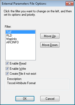
Former CADRaster versions support image parameters files in the RLD and TAF formats. This version additionally allows to import/export image parameters using files in formats supported by Map-Info and ARC/INFO applications.
You can specify the following options for each parameter file format:
Enable to Read
if selected CADRaster tries to find parameters file corresponding to currently opened image and read missing parameters,
Enable to Write
if selected CADRaster tries to find parameters file corresponding to currently saved image and write new parameters values,
Create file if not exists
Create file if not exists – Accessible only when Enable to write is selected. Controls whether a file in this format should be created if it does not exist.
Additionally you can define parameter file priority by sorting them in the list.
Save tab
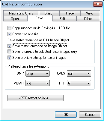
The Save tab allows you to defining the following options:
Copy subdocs while Saving As... TCD file
If this option is checked CADRaster saves not only TCD file with links to raster images or vector drawings, but also copy all subdocuments to new files. See the
RSaveAscommand description for more details. This option corresponds to theTCDSaveModeparameter from the [TSLRVC Library Settings] section in the cadrpro.ini file.Convert to one file
If option is selected CADRaster creates the multi-page destination file while converting multiple input files.
Save raster reference as R14 Image Object
If option is selected CADRaster saves in DWG document references to raster images opened by CADRaster using AutoCAD's Image Object. It allows to autoload raster file while opening DWG document in AutoCAD without CADRaster.
Save reference to selected raster images only
This option is accessible only while Save raster reference as Image Object is checked. It controls if all or only selected TCD subdocuments are saved as the references in DWG drawing.
Autoload geographical transformation
If this option is set on, then CADRastar tries to set geographical mapping taken from raster map.
Save preview bitmap for R14 images
This option is accessible only while Save raster reference as Image Object is checked. It allows the user save Image preview that may be seen in AutoCAD’s File Open dialog box.
Note
AutoCAD is equipped with limited set of raster format filters what may cause problems while trying to save Image Object with reference to file that format is supported by CADRaster but not by AutoCAD, e.g. VIDAR. In such case you should convert CADRaster image file to format supported by AutoCAD and after that save DWG drawing. You may also install additional raster filters available on Autodesk Web Site: http://www.autodesk.com
Preferred save file extension
Some raster formats may be saved under different file extensions. These include Tiff, Vidar, CALS and Bitmap. You can define preferred extension for each format.
Edit tab
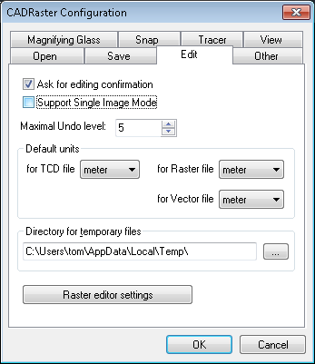
The Edit tab allows you to define the following options:
Support Single Image Mode
This option affects all file operations on a single image opened by the
ROpencommand. If the option is checked CADRaster supports the Single Image Mode, i.e. all file operations, likeRSaveorRSaveAs, are performed for single images directly on the image file, as to avoid creating a trivial TCD document that refers to one image only. If the option is cleared CADRaster creates a new composite document (TCD) for the image file being open, and attempts to save this new TCD document before closing. This option corresponds to the SingleDrwMode parameter from the [CADRaster General] section in the cadrpro.ini file.Ask for editing confirmation
If this option is checked CADRaster asks the user for confirmation before executing any editing. This option corresponds to the
ConfirmEditingparameter from the [CADRaster General] section in the cadrpro.ini file.Maximal Undo level
Option defines how many undo steps are allowed.
Default units
Default units for new TCD documents and raster/vector files without defined units.
Directory for temporary files
Path name to the disk directory where CADRaster’s temporary files will be created.
Raster editor settings button
The
Raster editor settingsbutton opens dialog with parameters controlling editing of color images. They are grouped in three boxes described below. All settings chosen during editing session are stored inINIfile.
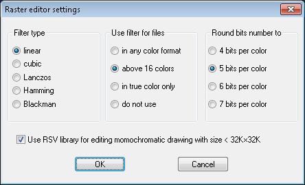
Filter type
Choice of filter type influences the way of calculating color of each pixel in transformed image during resizing, rotating and calibrating. The Linear and Cubic filters interpolate color value taking two or four adjacent pixels according to linear and cubic interpolation formulae, appropriately. The Lanczos, Hamming and Blackman filters take into account color values from six neighboring pixels. The default setting is Linear filter, which is the fastest one and precise enough for simple applications, like technical drawings and maps.
Use filters for files
Although precise choice of filter type may be individual for each type of image, the general decision when to use filter and when to not filter at all may be taken basing on image color format.
Option In any color format enables filtering always when transforming color and gray-scaled images.
Option Above 16 colors enables filtering for color and gray-scaled 256-palette images as well as for true-color images.
Option In true-color only limits filtering only to true-color images.
Option Do not use disables filtering at all.
The default setting is Above 16 colors.
Round bits number to
When the palette image is to be transformed using filtering, it requires converting to true-color format for processing and converting result back while storing. Rounding 8 bits per each basic color to some lower value, e.g. 7, 6, 5 or 4 bits may shorten converting and processing time, with slight degradation of color precision. Successive options named 4 bits per color, 5 bits per color, 6 bits per color and 7 bits per color declare which rounding is to be used. The default setting is rounding to 6 bits per each basic color.
Other tab
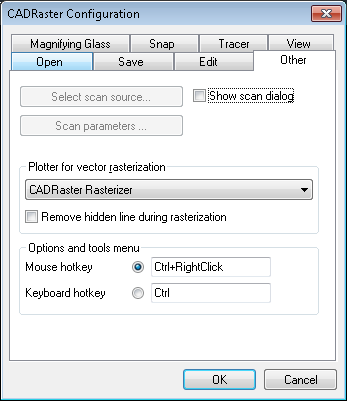
The Other tab allows you to define the following options:
Select scan source
This button activates the
RScanSourcecommand that is used for selection of the current scanning device (see description of theRScanSourcecommand).Scan parameters...
This button activates the
RScanParscommand that is used to set technical parameters of the scanning process (see description of theRScanParscommand).Show scan dialog
This check box controls whether the Scan dialog appears while scanning from CADRaster. If switched off the scanning process starts immediately after pushing Scan one page button on CADRaster toolbar.
Plotter for vectors rasterization
You can define plotter device used to rasterize vector entities in
RCreateandRInsertcommands. CADRaster displays only named platter devices. If you don’t define CADRaster will use plotter named “CADRaster Rasterizer” or current plotter.OTM hotkey
This option allows you to define CADRaster’s Options and Tools Menu hotkey. Default hotkey is
Ctrl+RightClick.


