
CADRaster consists of the startup program and several auxiliary libraries. Compressed versions of all these files and the installation program setup.exe are on the installation disks. Properly installed CADRaster can be run by double-clicking its icon in the Tessel Software Line folder.
In order to use CADRaster 15 you should have:
AutoCAD 2015, 2014, 2013 or 2012 for Windows,
at least 40 MB of free hard disk space,
mouse or other pointing device supported by MS Windows,
graphics card and monitor of at least VGA capabilities,
RAM as recommended to run AutoCAD, 2 GB or more,
Microsoft Windows 8.1/8 or 7 (AutoCAD 2014 does not support Vista),
Windows driver for your printer or plotter,
Hardware Lock in some version.
Important
Due to AutoDesk licensing policy, CADRaster is no longer available for AutoCAD LT 2015.
CADRaster Setup provides a quick and easy way to install this program on a user computer or file server. Setup uses a standard Windows user interface style. It contains all features and functions that are appropriate for Windows applications.
Important
Some problems can occur under Windows when user without assigned administrator privileges invokes Setup. We recommend that installation should be performed only by Administrators.
In addition Windows UAC (User Account Control) may interrupt installation and it's also recommended to turn it off/lower it to lowest position (only for installation process).
After loading CD-ROM, Tessel Software Line Setup starts automatically and lets you choose a product and its language version. In order to restart Tessel Software Line Setup, e.g. to install more products, re-load CD-ROM or open it in Windows Explorer and double-click TSLStartup.exe.
Setup tries to determine the location of AutoCAD automatically (using Windows registry). The AutoCAD’s location found by Setup is then presented in a dialog box, where you can confirm it or browse for another one.
Next, you can accept or choose an installation directory for CADRaster. It is recommended to use separate installation directories when installing multiple versions of CADRaster on the same machine, e.g. to test patches or new releases.
The default directory name is C:\Program Files\Tessel Software Line\CADRaster (if selected directory does not exist, it will be created, even with its parent directories).
After this phase Setup starts copying selected files to the installation directory. During this, Setup displays its progress bar.
Setup copies all CADRaster files to the chosen directory and creates the log of performed operations. Demo files are copied to the additional DOC subdirectory that may be deleted when no longer needed. The newly created program group Tessel Software Line contains the following items:
CADRaster to launch the program
CADRaster - Diagnostic mode to launch the program with registration of detailed system information and your actions in LOG file located in the CADRaster ’s configuration subdirectory
Read Me to show the technical notes in Notepad
Scripting in CADRaster Description of CADRaster's API
Help.
The default CADRaster INI file is copied to the CADRaster hidden directory: C:\Users\<username>\AppData\Roaming\Tessel\cadrpro.cfg\CADRPRO.ini.
It contains the option settings and the default attribute values for CADRaster commands.
Note
LTX and PRO naming convention:
LTX: the configuration subdirectory is named
CADRLTX.CFG, INI filecadrltx.iniand startup utilitycadrltx.exe.PRO: the configuration subdirectory is named
CADRPRO.CFG, INI filecadrpro.iniand startup utilitycadrpro.exe.
All further examples refer to CADRaster PRO version. If you have the LTX version, replace all the above names accordingly.
Important
When finished, Setup will ask if you want to launch CADRaster after closing Setup.
Please do not use this option and launch CADRaster manually afterwards.
Each product installed from Tessel CD or downloaded from http://tessel.com comes with a demo license.XML file that allows running it in Evaluation Mode accepting the enclosed demo drawings only.
After starting CADRaster you will get a warning message – click the Evaluation mode button in order to proceed.
In order to utilize the program normally, you must add a valid user license file.
If license file LICENSE.XML was delivered separately it must be copied to CADRaster installation folder.
You can view your license files using Notepad and manage them manually whenever necessary. Service Pack Disks downloaded from http://tessel.com do not contain license file – please contact your dealer or admin@tessel.se to get one.
Your License.xml file may require a hardware lock. In order to use hardware lock you must install Sentinel driver.
You may install them independently from Tessel CD or download them from http://www.safenet-inc.com/support-downloads/sentinel-drivers/.
Setup includes an integrated uninstallation program that allows users to uninstall CADRaster components cleanly and effectively and recover system resources such as disk space used by files and registry entries.
If, for some reason, you must uninstall CADRaster, run the Uninstall program icon or start Control Panel’s Programs and Features, select CADRaster and click the Uninstall button. Uninstall will remove most of the CADRaster program files and delete changes made to your Windows files. However, some files that are used by Windows or other programs may not be removed automatically, so it may be necessary to delete them manually.
To configure CADRaster to work with remote hardware key perform following steps:
Install Sentinel Drivers (Sentinel Protection Installer 7.6.5.exe) available on CADRaster installation CD in /tools/Sentinel/ folder. Please be sure to turn on installation of Sentinel Protection Server.
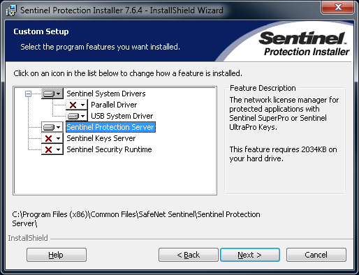
Plug USB hardware key to machine where Sentinel Protection Server was installed.
Install CADRaster on workstations. CADRaster will use hardware key from server. Information about location of USB hardware key will be broadcasted by Sentinel Protection Server over the network.
Try to run CADRaster without any additional configuration or modifications to your working environment, simply by double-clicking its icon. Except for installing CADRaster’s files and creating the Tessel Software Line program group and icons, Setup does not modify anything in your computer and leaves the existing installation of AutoCAD untouched. You will have to add Plotting output device named CADRaster Rasterizer.
CADRaster keeps various user settings in its INI file. The location of INI file may be specified according to the following syntax:
cadrpro.exe [/INI ini_file]
Setup places the INI file in the CADRPRO.CFG directory and creates a command line accordingly:
c:\Program Files\Tessel Software Line\CADRaster\cadrpro.exe /INI C:\ProgramData\Tessel\CADRPRO.CFG\cadrpro.ini
or
c:\Program Files\Tessel Software Line\CADRaster\cadrpro.exe/INI"C:\ProgramData\Tessel\CADRPRO.CFG\cadrpro.ini"
When installing multiple copies of CADRaster on the same machine you may need to maintain different INI files in separate directories.
In order to use other directories than CADRPRO.CFG created by Setup, the user must copy the cadrpro.ini file to its new directory and change the INI parameter accordingly.
When the INI parameter is omitted, CADRaster looks for the INI file in the user's Windows directory.
You may also use the cadrpro.exe command line to pass other parameters to AutoCAD and CADRaster.
Typically, you would put there the name of a DWG file to be opened by AutoCAD, and the name of a raster file (with a valid extension) or a composite document (with the TCD extension) to be opened by CADRaster in the same session.
For example, while having C:\Program Files\Tessel Software Line\CADRaster\DOC as the working directory, you could use the following command line:
C:\Program Files\Tessel Software Line\CADRaster\cadrpro.exe parcels.dwg townmap.tcd
In order to use a different working directory, you would need to specify full path names for the drawing files, as below:
C:\Program Files\Tessel Software Line\CADRaster\cadrpro.exe "C:\Program Files\Tessel Software Line\CADRaster\DOC\parcels.dwg"
    "C:\Program Files\Tessel Software Line\CADRaster\DOC\townmap.tcd"
While having CADRaster installed, you can still start AutoCAD without it, simply using the AutoCAD’s original icon that invokes acad.exe.
Using CADRaster as a user without Administrator privileges should not be hindered and all functions of CADRaster should work properly.
Although please remember (as it was said before), computer Administrator should always perform installation process. Also Administrator should run CADRaster for the first time after the installation, before user. He should point proper AutoCAD, check if CADRaster loads with correct license and if CADRaster ribbon is present. This is the safest method for using CADRaster on computer with users accounts.
Please note that User accounts have restricted access and rights on Windows OS. CADRaster does not enable to do things that normally User account would not be albe to do (for instance: saving or editing files that user do not have rights to)
When running with AutoCAD CADRaster is a separate ARX application that can be loaded on demand.
At the end of the installation process, Setup creates a program group Tessel Software Line with an item named CADRaster that
contains a command line invoking cadrpro.exe in the CADRaster directory and fills Windows system registry with information compatible with AutoCAD’s demand load specification.
When you start CADRaster using CADRaster group item it will be loaded automatically after starting AutoCAD.
If you start AutoCAD other way CADRaster will be activated after entering one of the following commands:
CADRASTER, ROPEN, RNEW, RCONVERT, RCREATE, RSCANONE, RSCANMANY, RSCANSOURCE, RSCANPARS, RCFG, RHELP, RABOUT
The AutoCAD’s DEMANDLOAD system variable that controls the demand loading operations must be set to 2 or 3 to make CADRaster autoloading upon command invocation.
When you have AutoCAD started together with CADRaster for the first time, you should define Plotting output device named
CADRaster Rasterizer according to the description below.
The device is needed only for RCreate and RInsert commands.
To add a new plotter device click on AutoCAD "A" main menu button. Then unfold more option for Print option and click on Manage Plotter.
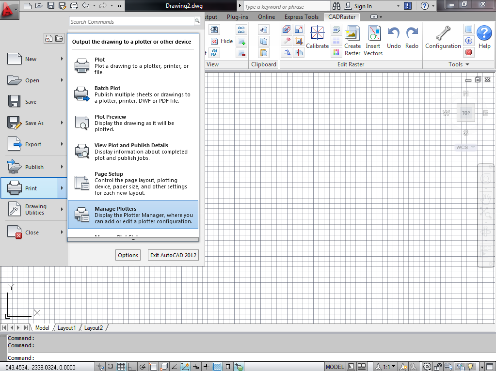
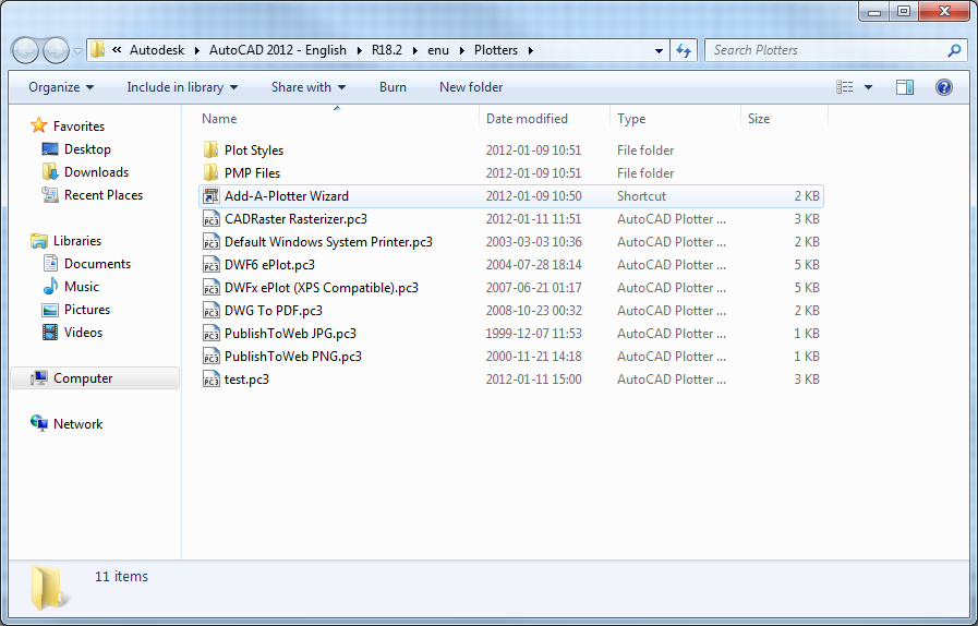
Windows Explorer window will pop up. Double click on Add-A-Plotter Wizard icon.
Using wizard dialogs, create a plotter named CADRaster Rasterizer using your system printer driver that you have already configured (do not use Heidi one - suggested device if you do not have one: HP LaserJet 2200).
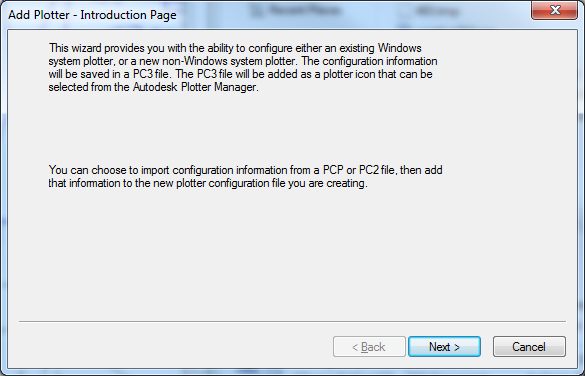
Click the Next button.
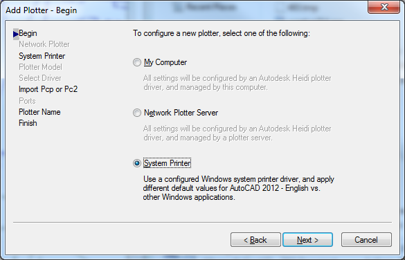
Select System Printer option and click the Next button.
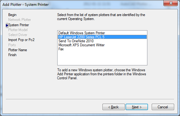
Select your Printer and click the Next button.
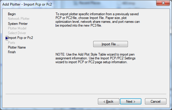
Do not import anything and just click the Next button.
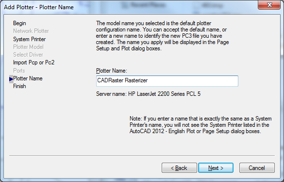
Name a plotter CADRaster Rasterizer and click the Next button.
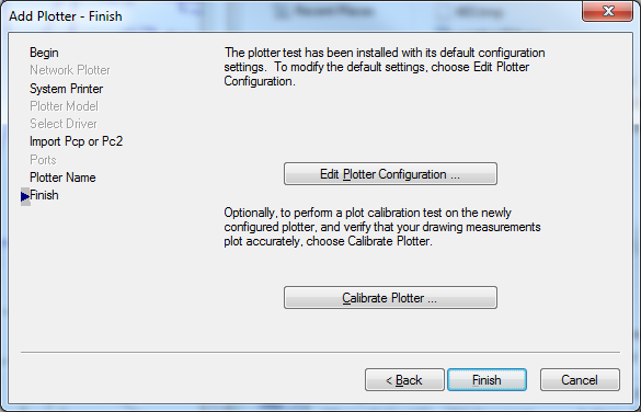
Click Finish button to complete adding a plotter.
Note
This wizard can also be accessed by using _plottermanager command.
RCreate and RInsert commands implementation changes list of standard paper sizes available for Default System Printer,
adding items named RasterizePortrait and RasterizeLandscape. Please ignore them while selecting the printout paper size.
CADRaster uses AutoCAD’s image object to display raster images.
The image object implemented by CADRaster does not support all features offered by original AutoCAD’s image object.
However some AutoCAD’s commands can be used in context of CADRaster’s image object.
You can use the IMAGE command dialog to inspect CADRaster’s image status.
The IMAGE command’s options Detach, Reload and Unload work as CADRaster’s RCLOSE, RON, ROFF commands respectively.
The frame displayed around raster image is controlled by the IMAGEFRAME command.
The ERASE command causes closing CADRaster image. The TRANSPARENCY command switches on/off transparent pixels handling.
The CADRaster’s RImport command allows you to convert AutoCAD’s image object to CADRaster’s image object.
Several image file formats allow images with transparent pixels.
Setting image transparency property to On allows AutoCAD to recognize the transparent pixels in CADRaster object, so that graphics on the screen show through those pixels.
By default, images are attached with transparency turned off.
AutoCAD transparency is controlled on a per-image object basis.
You can switch the transparency on/off using AutoCAD's TRANSPARENCY command or option Transparency from the Modify/Object menu.
CADRaster can display images with transparent color and with transparency mask. When an image containing such information is displayed, the transparent pixels are replaced with a color selected by the AutoCAD application. The selected color or pattern is usually the application's window background color.
CADRaster allows you to control displaying transparent colors defined in color image (TIFF images with Alpha channel or GIF images).
Monochrome image area is always displayed in transparent mode.
The Enable transparency option is available on the View page on the Configuration dialog.
By default, AutoCAD objects are drawn in the order they are created.
DRAWORDER command changes the display order of objects, moving one in front of another, for example.
Ordering ensures proper display and plotting output when two or more objects overlay one another.
An example of when ordering may be necessary is when a raster image is drawn over existing objects, obscuring them from the view.
The Send to back configuration option forces CADRaster image object to be automatically sent to back and displayed under vector entities.
CADRaster stores path name of opened raster image in the current DWG drawing.
CADRaster will automatically open raster image when you open a DWG drawing with stored raster image reference.
Additionally CADRaster can save in DWG file a reference to raster file that has been opened by CADRaster using AutoCAD's Image Object.
It allows autoloading raster file while opening DWG file in AutoCAD without CADRaster. When a TCD document is opened, CADRaster saves in DWG file references to all raster images embedded in TCD file.
There is also a possibility to save only selected TCD elements.
This feature is controlled by options located on the Save page on the Configuration dialog (see the section called “RCfg”).
Important
Due to AutoDesk licensing policy, CADRaster is no longer available for AutoCAD LT 2015.
Instructions below are for mentioned for older versions of AutoCAD LT.
CADRaster installation for AutoCAD LT is similar to installation for AutoCAD. The setup program creates all files needed to run CADRaster integrated with AutoCAD LT.
You start CADRaster by double clicking its icon. As for installation under AutoCAD LT there is no other way to have CADRaster started.
When you have AutoCAD started together with CADRaster for the first time, you should define Plotting output device named CADRaster Rasterizer
according to the description in the section called “CADRaster and AutoCAD”.
RCreate and RInsert commands implementation changes list of standard paper sizes available for Default System Printer,
adding items named RasterizePortrait and RasterizeLandscape.
Please ignore them while selecting the printout paper size.
An image frame displayed around CADRaster image can be controlled by the IMAGEFRAME standard AutoCAD's command.
Using CADRaster integrated with AutoCAD and other third-party applications sometimes may require more detailed configuration than described in the previous sections.
When AutoCAD is launched the following conditions must be observed for CADRaster to be run successfully:
AutoCAD should have defined a Plotting output device named CADRaster Rasterizer, as described in previous sections, in order to use
RCreateandRInsertcommand,AutoCAD must succeed while loading CADRaster’s ARX.
While using CADRaster integrated with AutoCAD LT the following conditions must be satisfied for CADRaster to run successfully:
AutoCAD must be started by means of CADRaster startup utility cadrpro.exe that assures proper CADRaster initialization,
CADRaster must be configured for using AutoCAD’s Default System Printer Driver in order to use
RCreateandRInsertcommand (AutoCAD LT),AutoCAD must successfully load CADRaster’s ARX.
While integrating CADRaster with applications that perform automatic initialization at the beginning of AutoCAD session there may be interference with CADRaster initialization procedure.
To work around the problem set SkipAutoLoading=1 variable in section [Options] of the cadrpro.ini file.
The option disables auto-loading of CADRaster extension files. After starting AutoCAD session with your application, just type any CADRaster command that will cause CADRaster to load and initialize.
Important
Due to AutoDesk licensing policy, CADRaster is no longer available for AutoCAD LT 2015.
If needed, CADRaster may be run with AutoCAD LT started by other applications.
To do so you should modify cadrpro(ltx).ini file in the section [CADRaster PRO(LTX/32) General].
First change the AutoCADPath= line by substituting Aclt.exe by path to another application and add line describing used version of AutoCAD.
CADRaster by default adds command line option '/c config_directory' when starting AutoCAD.
If your application cannot pass this options to AutoCAD, add line "SkipConfigDir=1" to this section.
An example bellow shows the modifications necessary to run CADRaster LTX or PRO with AutoCAD LT and Genius LT for Windows:
File: cadrltx.ini
[CADRaster LTX/32 General]

AutoCADPath=C:\Program Files\Autodesk\AutoCAD LT 2013\acadlt.exe
AutoCADVersion=
SkipConfigDir=1
File: cadrpro.ini
[CADRaster PRO General]
AutoCADPath=C:\C:\Program Files\Autodesk\AutoCAD LT 2013\acadlt.exe
AutoCADVersion=
SkipConfigDir=1
CADRaster Setup creates two program objects (icons).
One of them is a Diagnostic Mode - can be accessed easily from Windows Menu Start:CADRaster PRO - Diagnostic Mode.
The Diagnostic Mode icon should be used for starting CADRaster while debugging a problem with its functioning,
as described in the CADRaster User’s Feedback page (last page of User’s Guide or Report.txt file from Disk1 directory on CD or from CADRaster directory on your hard disk).
When reporting your problem to support@tessel.se, please include a filled feedback page and the CADRPRO(LTX).LOG file from CADRaster’s configuration subdirectory C:\ProgramData\Tessel\CadrPRO.CFG.
Magnifying glass may not work correctly on Windows 7 and newer with AutoCAD 2013, 2012, 2011 or 2010. It happens when hardware acceleration is enabled. To turn it off type “3dconfig” command. “Adaptive Degradation and Performance Tuning” dialog box will appear on the screen. Select “Manual tune” button. It will invoke “Manual Performance Tuning” dialog box. Uncheck “Enable hardware acceleration” option. Accept changes.
There are several limitations in 64-bit version of CADRaster:
RTRACE command does not work in 64-bit CADRaster.
Raster snaps were replaced with “Intelligent snap” in 64-bit version.
CADRaster can display and plot raster files of any width and height.
Editing operations are limited to raster images which width and height not exceed 32767 pixels.
This limit does not apply to composite documents that may have combined extents of all subdocuments.
When there is a need to edit greater image you should use the RSplit command to split big image into smaller parts.
Maximum dimension of plot that may be produced by CADRaster is 32767 pixels both for width and height. This limit is 65535 pixels under Windows NT.
CADRaster supports up to 512 subdocuments in a single TCD file.
Under AutoCAD LT raster tracing and snap functionality is not available inside floating viewports.
Under AutoCAD LT CADRaster commands are available only by clicking CADRaster's toolbar menu.
You can not activate CADRaster command entering it’s name from the keyboard. RSplit command is available when pressing RConvert button and Shift key at the same time.
RScanMany command is available when pressing RscanOne button and Shift key at the same time.
ClearDrawOrder command is not available.
The RCreate command uses AutoCAD’s PLOT command to rasterize vector entities.
Due to PLOT command limitations you can create raster image which dimensions can not exceed 65,535 pixels in X or Y directions.
If AutoCAD's variable TARGET is not set to 0,0,0 value (Parallel Projection or a Perspective View is used) CADRaster may eventually display raster image at a wrong position in AutoCAD coordinates.
This results in displacement of raster images in hybrid drawings caused by TARGET value.
To display raster in the right position, the TARGET variable must be set to 0 using DVIEW command:
Command: _DVIEW
Select objects: _all
CAmera/TArget/Distance/POints/PAn/Zoom/TWist/CLip/Hide/Off/Undo/<eXit>: _POints
Enter target point: 0,0,0
Enter camera point: 0,0,1
   CAmera/TArget/Distance/POints/PAn/Zoom/TWist/CLip/Hide/Off/Undo/<eXit>: _X

Command: TARGET
TARGET = 0.0000,0.0000,0.0000 (read only)
On some computers, when working with multiply drawing windows, CADRaster can hang and will not respond.
To fix this problem you can use parameter MdiSafeMode. Check it in the section called “[Options] section”.
