
To enter the Measurement mode, click the Measurements Drawing active button on the first toolbar. As a result you can see the Measurements panel with several fields and boxes. The second toolbar becomes active. You can use it to insert rectangles, circles, polylines, polygons and texts into the measurement drawing (see the section called “Defining spots and texts”).
In the Measurement mode, you may select several spots from the Object Overlay drawing (see the section called “Selection and grips edition”), or define your own entities in the Measurement drawing (see the section called “Defining spots and texts”).
After selecting group of spots under interest, you may use Insert Length / Area Measurement for Selected Spot buttons on the second toolbar to insert a text with a length or an area of currently selected spots. The inserted text becomes a part of the measurement drawing and can be edited as an ordinary text.
Use Insert Length Measurement for Selected Spots button to perform a length measurement action.
Use Insert Area Measurement for Selected Spots button to perform an area measurement action.
Use Delete Spot button or Del key from the keyboard to delete selected spots (these from the measurement drawing only).
Use Esc key from the keyboard to clear current selection.
Use Toggle Cross-hair button or F7 key from the keyboard to show or hide drawing cross-hair that assists you during drawing operations. Cross-hair is enabled only during editing or defining actions.
Use Toggle Ortho Snap Mode button or F8 key from the keyboard to activate or deactivate ortho snap. With Ortho Snap active, when you define lines close to horizontal, vertical or diagonal at 45 degrees, they become aligned automatically. Ortho Snap mode is enabled only during defining actions.
Click Measurements Drawing active button once again to close the Measurement mode.
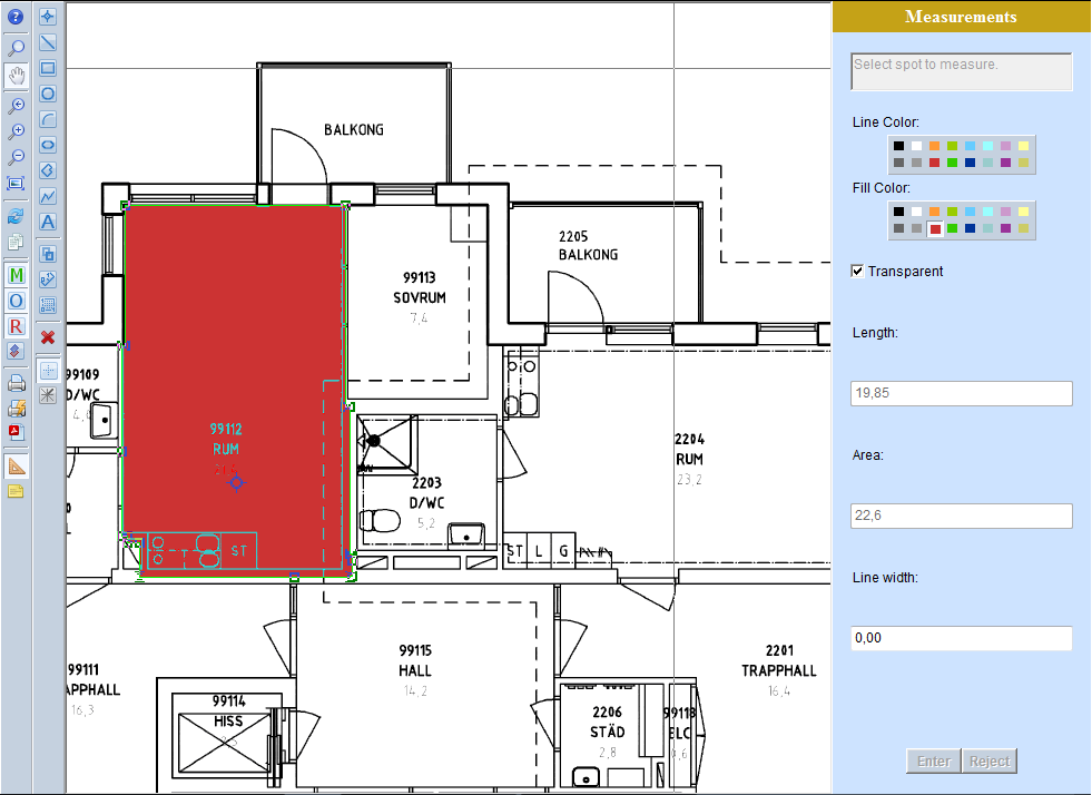
While you move the mouse over a spot, the spot's color is changing and becomes darker. If it is a text, its contents and style is displayed on the panel. For other spots its length, area and line width are displayed instead. A highlighted spot can be selected. To select a spot, click on it.
For spots selected from the Object Overlay drawing, you may inspect their properties only. For spots selected from the Measurement drawing, you may also change their properties and geometry.
For selected spots, their grips (little squares on corners) are displayed. The special one, circle-shaped grip in the middle of spot is displayed, either. While you move the mouse over a grip the cursor is changed to show that you can drag this grip. By dragging circular grip you can move a whole spot, by dragging a square grip you can change a shape of the spot.
To make multiple selection, click subsequent spots holding Ctrl key down. Notice that a length and an area displayed on the panel is the sum of lengths and areas of all but texts spots that the selection consists of.
Use Line Color and Fill Color palettes to choose an appropriate color for selected spots. For all but text entity the Line width box is active. If all selected spots have the same line width its value is displayed in the box, otherwise it is empty. You can use keyboard to enter a new value.
For selected text, its contents and style are displayed. You can choose a style from the list of styles that are available in the system. You can change a content of the text according to your requirements.
To confirm changed colors, or values written into field boxes, use Enter key from the keyboard or press the V Enter button. To reject entered values, use Escape key from the keyboard or press the X Escape button.
To define a rectangle, choose the Insert Rectangle button on the second toolbar and then click with the left mouse button the point of the drawing where you want to have the first rectangle corner. You can see the coordinates of this point in the X coordinate and Y coordinate boxes that are displayed on the Measurements panel. Then drag the mouse and click the point where you want the opposite corner is to be defined. The X and Y distances from the previously entered point are displayed in X distance and Y distance boxes on the panel. While dragging the cursor, the shape of the rectangle is displayed.
To define a circle, choose the Insert Circle button on the second toolbar and then click with the left mouse button the point of the drawing where you want to have the center of the circle. You can see the coordinates of this point in the X coordinate and Y coordinate boxes that are displayed on the Measurements panel. Then drag the mouse and click the second point. The distance between the clicked points defines the radius of the circle. While dragging the cursor, the shape of the circle is displayed.
To define a polygon, choose the Insert Polygon button on the second toolbar and then click with the left mouse button the point of the drawing where you want to have the first vertex of the polygon. You can see the coordinates of this point in the X coordinate and Y coordinate boxes that are displayed on the Measurements panel. Then drag the mouse and click the points where the subsequent vertices are to be defined. The X and Y distances from the previously entered point are displayed in X distance and Y distance boxes on the panel. To stop defining vertices click the right mouse button. On a popup menu that is displayed choose Accept / Cancel / Continue to accept polygon, cancel the action or continue defining vertices appropriately. While dragging the cursor, the shape of the polygon is displayed.
To define a polyline, choose the Insert Polyline button on the second toolbar and then click with the left mouse button the point of the drawing where you want to have the first vertex of the polyline. You can see the coordinates of this point in the X coordinate and Y coordinate boxes that are displayed on the Measurements panel. Then drag the mouse and click the points where the subsequent vertices are to be defined. The X and Y distances from the previously entered point are displayed in X distance and Y distance boxes on the panel. To stop defining vertices click the right mouse button. On a popup menu that is displayed choose Accept / Cancel / Continue to accept polyline, cancel the action or continue defining vertices appropriately. While dragging the cursor, the shape of the polyline is displayed.
To define a text, choose the Insert Text button on the second toolbar and then click with the left mouse button the point of the drawing where you want to have the left lower corner of the text. You can see the coordinates of this point in the X coordinate and Y coordinate boxes that are displayed on the Measurements panel. Then continue as you define a rectangle. While dragging the cursor, the shape of the rectangle with text content "Text" is displayed.
Use Line Color and Fill Color boxes to choose an appropriate color for the spot that you are defining.
During defining the spot, you can use the keyboard to enter numerical values to the X coordinate and Y coordinate boxes (for first point) and to X distance and Y distance boxes (for subsequent points).
Use the Tab key from the keyboard to start writing first coordinate, Tab key again to start writing the second one, and confirm with Enter key or press the V Enter button to set the point. To reject entered values, use Escape key from the keyboard or press the X Reject button.
Use Esc key to close the Define mode end go back to Measurement mode.
For additional options that can be enabled for Mesurement Mode please refer to Administration manual to the section called “Save measurement vectors improvement” and, the section called “Color palette configuration in Measurement mode”.
