
Each drawing file can have an attribute file associated with it, where the drawing’s technical parameters are stored. It is especially useful to store the parameters that can not be stored in the drawing file itself due to its format limitations. Some image file formats allow storing more parameters than others do. The values of image parameters are saved in the image file, if the image format allows for it, and in an additional parameter file with the same name as the image file name but with TAF (Tessel Attribute File) extension. The TAF file is located in the same disk directory as the image file.
Parameters saved in the image file override parameters saved in the additional parameter file (TAF).
Creating and using of attribute files can be disabled using the BRAOpenOptions parameter in corresponding program .ini file (see ).
A TAF file is a text file formatted in sections (like INI files). If the image file is a multipage raster file, each section describes a separate page.
The first page is described by the [RasterImageParams] section, the second page is described by the [RasterImageParams.1] section and so on.
Parameters of a drawing file in one of vector formats (DWG or DXF) are specified in the [VectorDrawingParams] section.
Thus it is possible to have two drawing files with the same file name and different file name extensions in one disk directory: one in raster format and one in vector format and to use a common TAF file for them.
Their parameters are located in different sections of the same TAF file. Vector drawings use only two parameters: Units and Orientation.
Section name line syntax: [<section_name>]
Parameter line syntax: <Parameter_name>=<Parameter_value>
Parameters description:
Units - the code number of units used to define the insertion point of the image; one of the following values:
1 | inch |
2 | foot |
3 | yard |
4 | mile |
5 | millimeter |
6 | centimeter |
7 | meter |
8 | kilometer |
Color - the color number from the AutoCAD palette (for monochrome raster images only)
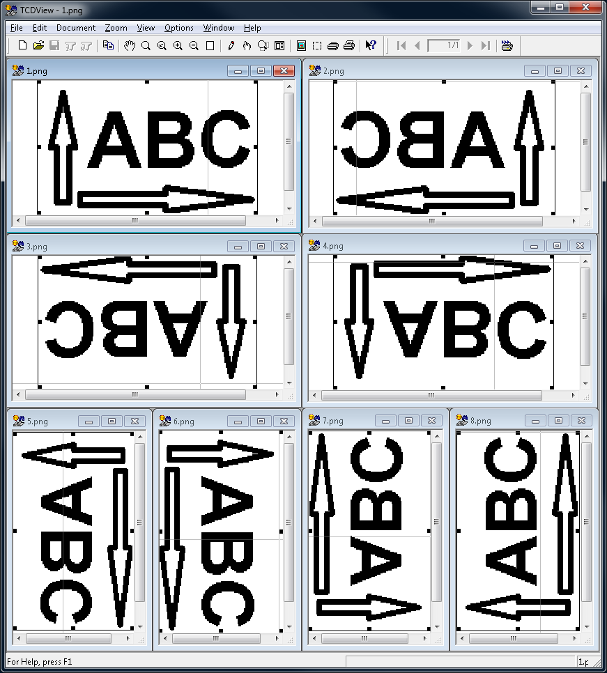
Orientation - the image’s orientation. Defined in raster terms (lines and columns of pixels) but maintaining analogical meaning also for vector drawings. The Orientation can have one of the following values:
1 | first line at the top, first column at the left side |
2 | first line at the top, first column at the right side |
3 | first line at the bottom, first column at the right side |
4 | first line at the bottom, first column at the left side |
5 | first line at the left side, first column at the top |
6 | first line at the right side, first column at the top |
7 | first line at the right side, first column at the bottom |
8 | first line at the left side, first column at the bottom |
See also the picture below for the reference to coresponding above numbers.
XInsertionPoint - X coordinate of the lower left corner of the image;
YInsertionPoint - Y coordinate of the lower left corner of the image;
XScale - the horizontal scale of the image;
YScale - the vertical scale of the image;
XResolution - image’s horizontal resolution;
YResolution - image’s vertical resolution;
Length - the number of pixels in a single raster line;
Width - the number of raster lines;
Comment - image’s description or a remark text.
