Geographical Mapping Systemsoption are available from context menu after clicking Right Mouse button while holding left Ctrl key while using CADRaster.
While in HyperDoc it can be open from Drawing menu.
Select Geographical Mapping and then Select... to open Geographical Mapping dialog box where you can select mapping.
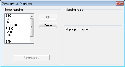
In the GEO system coordinates of all objects are expressed in geographical degrees (it concerns all entered, displayed and edited coordinates also). The coordinate system is orthogonal with the geographical degrees as units on the both axes.
While importing vector drawings stored in natural geographical coordinates, various logical units may be associated with it.
You can declare which units of drawing should be regarded as degrees, activating the Parameters... button on the Geographical Mapping dialog to display the Set GEO Parameters dialog box.
Choose appropriate units from list of available units.
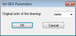
Use the OK button to accept the selected mapping parameters and close the dialog. Use the Cancel button to withdraw changes made (if any) and close the dialog.
The Gauss-Krüger projection system is a conformal, cylindrical, transverse Mercator projection of the earth's ellipsoid surface made on the plane in such a way, that the center meridian is transformed without distortions and the symmetry against the meridian is also preserved.
Generally, the transformation of the whole surface of the earth's ellipsoid (or a large part of it) results in the high level of distortions. To make it acceptable, the ellipsoid is divided to meridional strips, each 3 or 6 degree wide. Then subsequently, the strips are projected on the cylindrical surface, which is tangent to the ellipsoid along the central meridian of each strip. To balance the error level along distance from the central meridian the scale factor is introduced. The scale factor 1.0 means that there is no error on the center meridian points and a maximal error is on the both edges of the strip. A smaller then one (1.0) scale factor balances the error for the central meridian points with the error on the strip edges.
After the projection, the central meridian of strip and the equator are perpendicular. This is the reason to base on them the local strip's coordinate system, with axes traditionally marked as X for north direction and Y for east direction. Additional offset in the X-Y coordinate system allows avoiding negative coordinates values to the left from central meridian and below the equator.
The maximal distortion in a 3-degree strip is 17 cm/km and in a 6-degree strip – 70 cm/km. It is much less then the printed map's accuracy, which is about 0.2 mm.
The P42 system is Gauss-Krüger (Transverse Mercator) system with the following features:
maps with scales from 1:10 000 till 1:500 000 are based on 6-degree strips;
maps with scales from 1:5 000 and greater are based on 3-degree strips.
Activate Parameters... button on the Geographical Mapping dialog to display the Set P42 Parameters dialog box..
It contains the list box with all possible values of strip centers (meridians) and two radio buttons to make choice between 3 and 6 degree strip width.
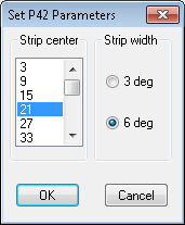
The following parameters are fixed in P42 system:
scale factor = 1.0000;
parallel = 0.00 deg;
X offset = 0.00 m;
Y offset = zone number + 500 000.00 m;
ellipse by Krasovsky.
Use the OK button to accept the selected mapping parameters and close the dialog. Use the Cancel button to withdraw changes made (if any) and close the dialog.
The Universal Transverse Mercator (UTM) system is Gauss-Krüger (Transverse Mercator) system with the following features:
it provides world coverage between the latitudes 84° N and 80° W (each zone extends between the latitudes);
the zone numbering system is that the first zone has its western edge on the meridian 180° and the zones proceed eastwards to zone 60 which has its eastern edge at 180° longitude;
each zone is 6° longitude in width;
the Eastings of the origin of each zone (Y offset) is assign the value 500 000 m.
Activate Parameters... button on the Geographical Mapping dialog to display the Set UTM Parameters dialog box..
It contains the combo box with all possible central meridian positions and edit box to write a value of Y offset (usually 500 000 m).
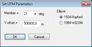
The following parameters are fixed in UTM system:
scale factor = 0.9996;
strip width = 6°;
parallel = 0.00°;
X offset = 0.00 m in northern hemisphere; 10 000 000 m in southern hemisphere;
ellipse by Bessel.
Use the OK button to accept the selected mapping parameters and close the dialog. Use the Cancel button to withdraw changes made (if any) and close the dialog.
The Deutsche Heeresgitter (DHR) system is Gauss-Krüger (Transverse Mercator) system with the following features:
it is designed to cover Germany area;
strip width is assigned 6° for military use and 3° for cadastral, municipal and civil engineering use (known also as Deutsche Reichsgitter - DRG);
Activate Parameters... button on the Geographical Mapping dialog to display the Set DHR Parameters dialog box..
It contains the combo box with all possible central meridian positions (usually 9°) and edit box to write a value of Y offset (usually 500 000 m preceded by zone number).
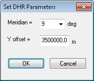
The following parameters are fixed in DHR system:
scale factor = 1.0000;
strip width = 6°;
parallel = 0.00 deg;
X offset = 0.00 m;
ellipse by Bessel.
Use the OK button to accept the selected mapping parameters and close the dialog. Use the Cancel button to withdraw changes made (if any) and close the dialog.
The Generic Transverse Mercator (GTM) system is Gauss-Krüger (Transverse Mercator) system with all the possible configurable parameters.
Activate Parameters... button on the Geographical Mapping dialog to display the Set GTM Parameters dialog box.. It contains:
the list box with the most common use ellipses;
the group box with the chosen ellipse major ax and perimeter values (the edit boxes are enabled for the Custom ellipse only);
the Origin group box with Meridian and Parallel edit boxes;
the Offset group box with X offset and Y offset edit boxes;
the Scale edit box.
Family of geographic transformations based on stereographic projection (GOS - Generic Oblique Stereographic). New geographic mappings for Poland area: P65, GUGiK80 (based on Pulkovo 42 datum with Krassovsky ellipsoid) as well as P1992 and P2000 (based on GRS80 ellipsoid) have been implemented. Mapping UTM has additional choice of ellipsoid: Hayford-1924 (previous default) and WGS84 (new one).
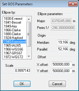
Use the OK button to accept the selected mapping parameters and close the dialog. Use the Cancel button to withdraw changes made (if any) and close the dialog.
Properties (types and parameters) as well as methods (transforming between geographical and ortho coordinates) of geographical transformations have been exposed via Automation interface of CADRaster. Additionally, transformation between BLH and XYZ coordinate systems have been implemented and exposed as well.
Information about geographical mapping to be used while viewing raster drawing, can be stored in and retrieved from Tessel Attribute File (*.TAF file).
You may activate "Geographical Mapping - Load" option to force the mapping to be active.
Alternatively, you may select some mapping and choose "Geographical Mapping - Save" option to associate it with the drawing.
Both options are enabled only if there is only one raster drawing opened, or (in case of composite documents containing several raster drawings) only one raster drawing selected.
The same geocoding information, together with georeferencing data, are stored and retrieved in
GeoTIFF format in TIFF drawing files and in MapInfo (MIF) format in *.TAB files
(if selected after activating "Configuration - Open tab - Parameters file options" button).
Possibility of retrieving geocoding information stored in GeoTIFF or MapInfo format is limited to geographical mappings implemented in TSLGEO dynamic link library.


