
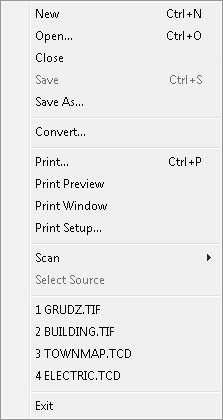
The File menu commands are used for selection of documents to be opened, for selection of scanner and for starting the scanning, for document printing or conversion to different raster formats, for closing the documents and for exiting the program.
This menu also shows up to four file names of documents that were most recently used. Clicking on a name opens the selected document.
Names of these files are stored in the TSLSV.INI file in the section [Recent File List].
The New command is used to create a new empty composite document. Drawings can be added to such a document using the Add Subdoc command from the Document menu.
The Open command is used for selection of a composite document or a single drawing file, which is to be opened by SuperView.
In the dialog box, launched by the Open command, you should select a needed file format type, disk drive and directory on this drive.
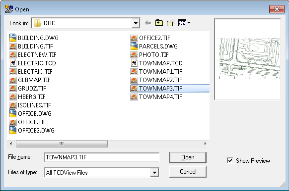
As a result of these selections the program will display the list of all files in the selected directory with the selected extension. Every change of the format type or of a disk and/or directory is immediately reflected in the displayed list of files. Opening of a document file from that list is done by its selection with the left mouse button click and then clicking the OK button; the left mouse button double click on the file name on the list is an alternative method.
When you select raster or vector drawing file for opening, SuperView creates a new composite document, which contains a single drawing just selected.
When the Shift or Control key is pressed, it is possible to select multiple file names.
When the Shift key is pressed, you select only the first and the last of files you want to open and all the files between them on the list will also be selected.
When the Control key is pressed, you select multiple file names by clicking on each of them separately - they do not have to be neighbours on the list.
After selecting all desired file names, you click the OK button and all selected files are opened - each in its own window.
The Open command can be always used, i.e. you can view more then one document at any given moment.
Documents are displayed in separate windows. Only one of them is active at any given moment - its title bar is displayed in a different color - and all commands apply to this document.
To make another document window active, you simply click this window area. If it is invisible, you select it from the list available in the Window menu.
The Window menu is also used for document windows ordering.
The Close command is used to terminate displaying a document by closing the file with its contents.
When multiple documents are open simultaneously, the command refers only to the active document.
When in the course of the session the document has been modified, the user is asked to decide whether to save the changes.
If positive, the document will be saved in the same file from which it has been loaded (opened).
If a composite document being closed was created by opening a single raster or vector drawing and no viewport or parameter changes were made,
then Close does not ask for saving this document and, if it is to be saved, it must be done explicitly using the Save As... or Save command.
This facilitates the viewing of single raster and vector files without creating trivial composite documents that refer to one file only.
The Save command is used for saving the changes to the current composite document in the same file from which the document has been loaded (opened).
The Save command is available if the current document is a new document or if it has been modified using commands from the Document menu.
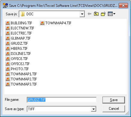
The Save as... command is used to save the current document in a file different from which that document has been loaded.
When several documents are loaded, the Save as... command refers only to the active document.
In the dialog box, invoked by this command, you select a disk drive and a directory on this drive.
Then enter, or select from the displayed list, a file name with TCD extension.
If the file with the entered name exists, the program launches additional dialog box that asks you, if you want to overwrite the existing file.
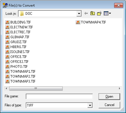
The Convert... command is used to create a new version of a drawing in a raster format different than the original.
This command launches the dialog box named Input File, otherwise identical to the dialog box in the Open command and serving the similar purpose of the drawing file selection.
The selected file in this case will not be displayed but only read in order to be converted. After the input file is selected, the analogical dialog box Output File appears.
It allows to select a new drawing format, file name and destination (disk drive and directory).
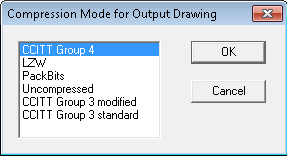
If the newly selected file format supports multiple compression modes, an additional dialog box appears for precise selection of a desired file subformat.
The list of output file formats and compression modes depends on the format of the converted (input) file. The full list of formats that are available in each case is displayed in the File Type list box.
When multiple input files are selected, they are converted to a single file in one of multi-page formats (TIFF, DCX).
Each page in the resulting document contains data from the corresponding input file.
You can suppress this feature and convert each input file to a separate destination file by setting the ConvertToOneFile parameter in
the TSLSV.INI file to 0 (see the section called “TSLSV.INI file”).
The Print command starts printing selected document or launches the Print dialog box that is based on which printer was chosen in Print Setup dialog (see below).
So before printing please first open Print Setup dialog
The Print Preview command launches Page Preview window. This is the window showing what will be printed - it allows setting the layout of the printed document view on the displayed paper sheet.
Print Window command starts launches resizeable box on current document that can be used to control the printing scale and area of picture to be printed.
You can grab each corner of the box using Left Mouse Button and drag it to set the area for printing.
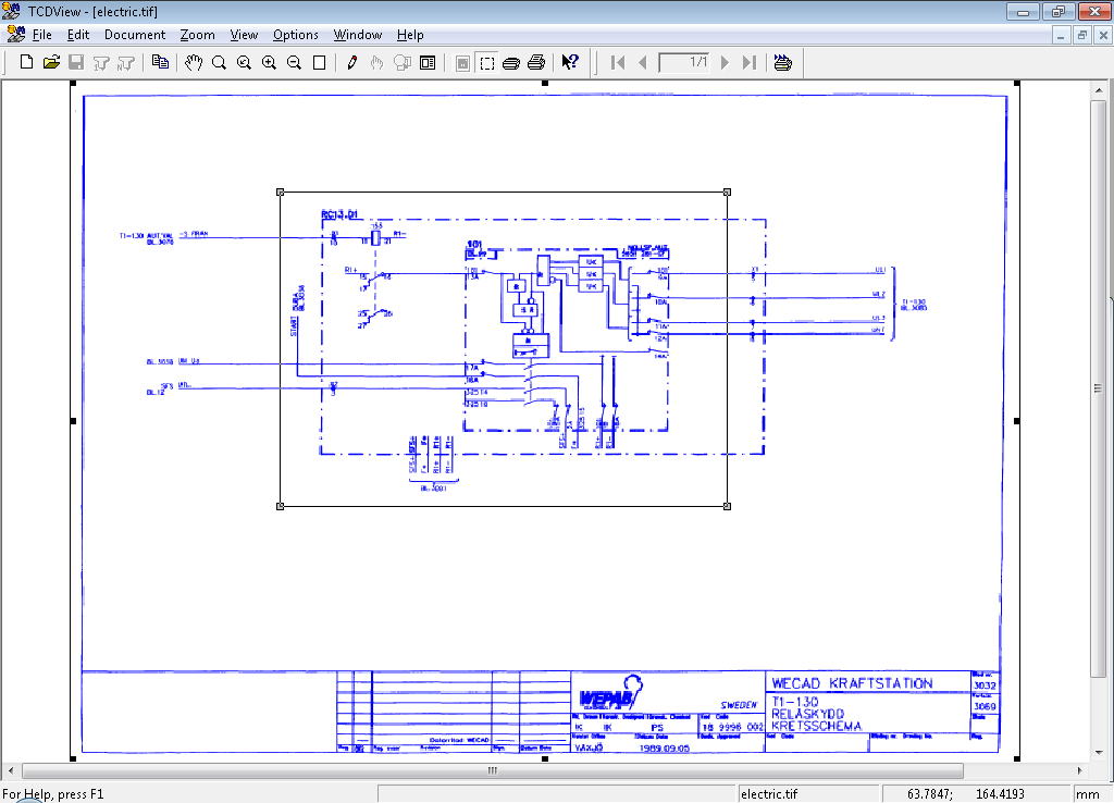
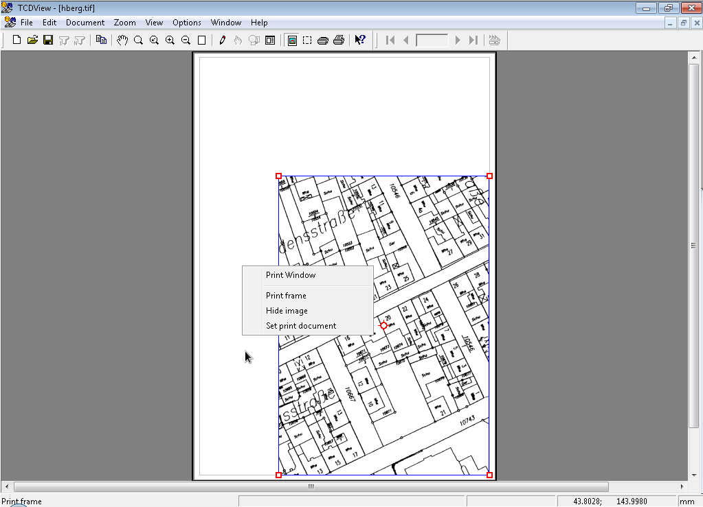
When you have set area for printing, click Right Mouse Button to open context menu:
Acceptcommand cuts the picture to the selected area and enables new commands from context menu.If you have focus on hole printing page (by default after clicking Accept command) then in context menu you will have:
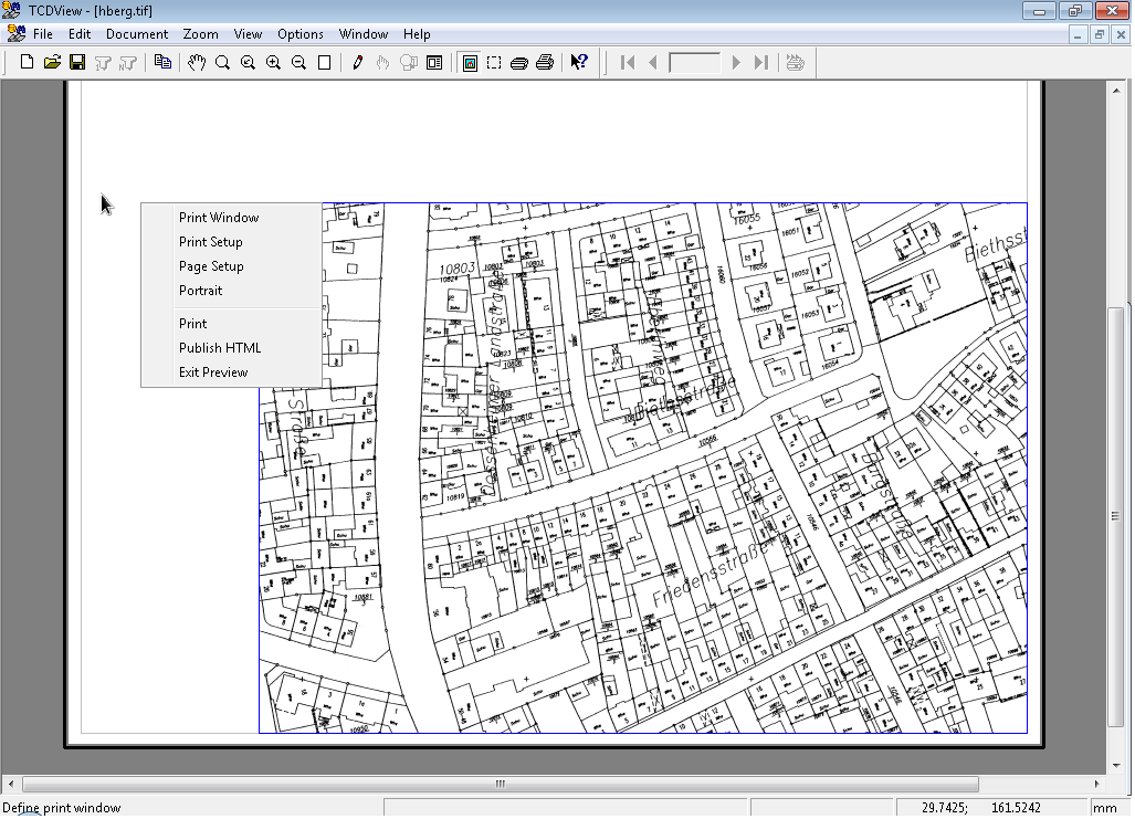
Print Window- goes back to Print Window where you can again choose area for printing,Print Setup- opens Print Setup dialog (see below for more information on this dialog),Page Setup- opens Margins dialog where margins can be set,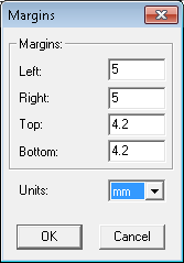
Portait/Landscape - changes the picture orientation.
Print- starts Printing based on the chosen printing configuration selected in Print Setup dialog,Publish HTML- creates simple HTML page with the image for print linked to it.Exit Preview- goes back to standard SuperView screen.
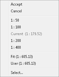
If you have focus on the area selected for printing, (it can be easily distinguish by red squares on each of the area corners) than this context menu will show:
Cancel- goes back to Print Preview look,Various scales values that can be chosen for the printing area,
Select...- opens a dialog where you can set your onw scale.
The Print Setup... command launches the Print Setup dialog box.
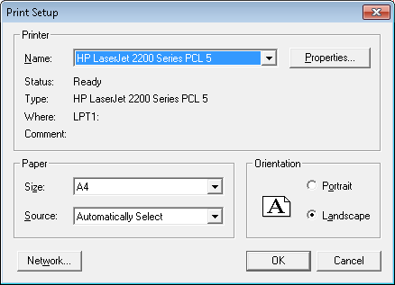
In this dialog box it is possible to:
select the current print device from the list of available devices,
change some printer parameters (e.g. print orientation, paper size, paper source),
set print quality parameters in the Properties dialog box, which is displayed after pressing the
Properties...button.
New printer drivers can be added and printer to port mappings can be changed using the MS Windows system Control Panel.
The Scan command is used to start scanning of a new document. Depending on the kind of scanned document (single-page or multiple-page) one of two options can be selected:
One page,
Multiple pages.
Before scanning it is necessary to select a file name and a raster format of the drawing that will be created as a result of scanning. After scanning, a new composite document is created, containing a single raster file with the scanned image.
This command starts scanning of a single-page document.
Depending on the type of the selected scanner it may be necessary to start scanning physically, e.g. by pressing a button on the scanner. Some scanners can start scanning automatically, others can display their proprietary window with information about scanning progress. The scanned document is then displayed in a window labelled with a temporary name, e.g. SCAN_1.
This command starts scanning of a multiple-page document.
The process of multiple-page scanning is similar to the single-page scanning. After each page the dialog box appears and informs about the number of pages scanned so far. Four buttons are available (some of them can be disabled, depending on the situation):
Next- confirms the last scanned page and starts scanning of the next one;The Same- repeats scanning of the last page;Close- confirms the last scanned page and stops scanning; the file will contain the number of pages as currently displayed in the dialog box;Cancel- stops scanning and discards pages scanned so far.
The first page of the scanned document is displayed in a window labelled with a temporary name, e.g. SCAN_1.
The Select Source command is used for selection of the current scanning device. The Select Source command is relevant only when more then one scanner is installed.
Click a name and press the Select button to choose a scanning device. Particular scanning parameters can be set using the Scan Parameters command from the Options menu.
The list shows only TWAIN-compatible devices that have been properly installed.
When the part of scanning software that is responsible for cooperation with applications that use the TWAIN standard is present,
the device should appear on the list of available scanners (no additional installation on the part of SuperView is required).
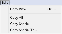
The Copy View command is used to transfer the current view of the current document to the MS Windows system Clipboard.
Only the currently visible part of the document is transferred in its current scale.
Independently of the values of CopyEmbedded and CopyLink variables in the TSLSV.INI file, the Copy View command does not allow to embed or link data from the Clipboard to other applications.
The copy of the document view can be prepared only in DDB bitmap, DIB bitmap and metafile formats.
The Copy All command is used to send a copy of the current document to the MS Windows system Clipboard.
Basically it is used for simple interchange of documents between different MS Windows applications.
The Copy All command, unlike the Copy View command, prepares data from the whole document, no matter what the current view is.
It is also possible to define sizes and resolution for preparing a copy of the document.
Four variables are used for this purpose, Width, Height, Xres and Yres, all with the ClipboardCopy prefix defined in the TSLRVC Library Settings section of the TSLSV.INI file.
All these parameters can be changed by editing this file. New values are used next time the program is run.
The default settings of variables result in making a copy of a document that is 6.67 inches wide and 5 inches high with 96 dots per inch resolution. These parameters reflect the size and resolution of a typical monitor screen. A document will be scaled in such a way that it will cover the demanded area as fully as possible. A document can be copied in every available format (embedded object, link, bitmaps and metafile).
When multiple documents are displayed, the command acts only on the current document.
The Copy Special command is used for sending a copy of the current document to the MS Windows system Clipboard.
Basically it is used for an interchange other than simple interchange of documents between different MS Windows applications (see Copy All).
The command also copies the whole document, no matter what the current view is, but it uses parameters defining sizes and resolution of the document copy, different than the Copy All command.
These parameters are read from four variables, Width, Height, Xres and Yres,
all with the ClipboardCopySpec prefix defined in the TSLRVC Library Settings section of TSLSV.INI file.
All these parameters can be changed by editing this file. New values are used next time the program is run.
The default parameter values are prepared for 1:1 copying of documents in a typical fax format, i.e. 8 inches wide, 11 inches high, 96 dots per inch of vertical resolution and 203 dots per inch of horizontal resolution.
If the current document is greater than the demanded copy size, then it is scaled, so that it fills the requested copy size as fully as possible. A document can be copied in every available format (embedded object, link, bitmaps and metafile). When multiple documents are displayed, the command acts only on the current document.
The Copy Special To... command is used to make a copy of a document and save it to a selected file.
The width, height and resolution of created file are defined by the same parameters as in the Copy Special command.
The default parameters are set for copying to the A4-size page with a resolution typical for fax devices.
These parameters are read from four variables, Width, Height, Xres and Yres,
all with the ClipboardCopySpec prefix defined in the TSLRVC Library Settings section of the TSLSV.INI file.
All these parameters can be changed by editing this file. New values are used next time the program is run.
Saving a document in a new file can be combined with changing of the raster format and compression mode (see the Convert... command from the File menu).
When multiple documents are displayed, the command acts only on the current document.
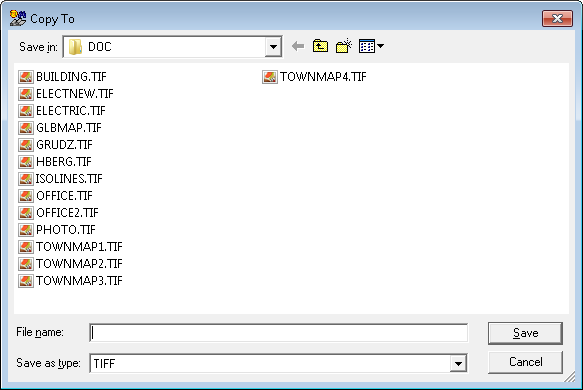
(CTXTDEF:HIDD_SUBFORMAT)In the dialog box invoked by the Copy Special To... command you select a raster format type, a disk drive and a directory on this drive.
Next, you enter a file name with an extension that is appropriate for the selected raster format type. You may type it or select it from the displayed list of files with previously chosen extension.
If another file with the same name exists, the program asks you, if you want to overwrite the existing file.
If the selected output file type supports multiple compression modes, you can choose a compression mode in an additional dialog box Compression Mode for Output Document, which opens automatically.
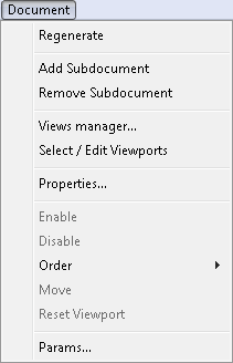
The Document menu commands are used for composite document management. Using these commands it is possible to add and delete drawings to/from composite document, to change the order in which they overlap one another, to change properties of individual drawings belonging to the composite document (like their position, current page or visibility status) and to change parameters of the composite document as a whole (e.g. its presentation units).
For each component drawing its visible area, called viewport, is defined.
Initially (after adding the drawing to the document) it is set to full drawing extents.
Viewport areas can be changed after entering the Selecting mode using the Selecting command from the Document menu (also available on toolbar).
The Reset Viewport command sets the viewports of currently selected documents to their initial size (full extents of each respective drawing).
Entering the Selecting mode is also necessary when one of:
Enable, Disable, Change Link..., Copy..., Order,
Move, Properties..., Undo, Redo commands from the Document menu is to be issued,
because each of these commands operates on currently selected drawings (Change Link..., Copy..., Properties..., Undo,
Redo are active only when exactly one drawing is selected).
SuperView is performance-optimized for viewing large raster and vector documents. For each open document it keeps a full view of this document.
This feature allows to execute the Zoom-Extents command very fast. In some situations, however, the use of full view cache can somewhat decrease the quality of document display.
In this case the user can issue the Regenerate command which forces full resolution redraw without using the stored view.
Storing and using of full view cache can be disabled by setting the UseFullViewCache parameter in the TSLSV.INI file to 0 (see the section called “[TSLRVC Library Settings] section”).
The Add Subdocument command from the Document menu is used to add a new component drawing to the current composite document. It launches a dialog box for selection of a drawing to be added.
The Remove Subdoccument command from the Document menu removes currently selected drawings (see the Selecting command) from the current composite document. Of course, it does not delete the drawing’s file.
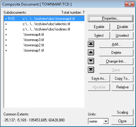
The Properties... command launches the Composite Document dialog box.
This dialog box groups together most of commands available in the Document menu (described in following sections).
In addition to buttons for issuing these commands, the Composite Document dialog box displays a list of component drawings in the current composite document.
Using this list it is easy to select drawings as arguments to commands that operate on specified drawings.
The Composite Document dialog box lists the component drawings in four columns. The first, the second and the third column show the drawing status information, and the fourth one displays drawing file names. The first column contains plus sign (+), if the corresponding drawing is enabled (visible) or minus sign (-), if the drawing is disabled (invisible). The second column can be empty or it can contain either the “N/A” text, if the drawing’s file can not be found, or the “R/O” text, if the drawing is open in the read-only mode. The third column contains “S” character, if the corresponding drawing is selected.
If the Properties... command is issued in the selecting state (see description of the Selecting command), currently selected drawings will be shown as selected in the dialog box list.
After closing the Composite Document dialog box in the selecting state, drawings which were selected in the dialog box list remain selected and the other drawings are not selected.
This way it is possible to perform drawing selection from the list of component drawings.
This selection method is alternative to the mouse click selection method described in the Selecting command section below.
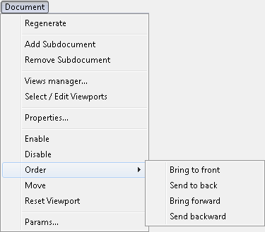
The Order command from the Document menu allows to control the order in which component drawings overlap one another, when the composite document is displayed or printed.
The Order command has four subcommands described below.
Each of them moves selected drawings on the composite document’s drawing list.
The Bring to front command moves selected drawings to the front end of the composite document’s drawing list, i.e. makes them cover the other drawings.
The Send to back command moves selected drawings to the back end of composite document’s drawing list, i.e. puts them under the other drawings.
The Bring forward command moves selected drawings (see the Selecting command) one step in the front direction on the composite document’s drawing list,
i.e. makes them cover the drawing which preceded them immediately on the composite document’s drawing list.
Issuing the Bring forward command sufficient number of times is equivalent to issuing the Bring to front command one time.
The Send backward command moves selected drawings one step in the back direction on the composite document’s drawing list,
i.e. puts them under the drawing which followed them immediately on composite document drawing’s list.
Issuing the Send backward command sufficient number of times is equivalent to issuing the Send to back command one time.
The Move command from the Document menu allows to change the position of the selected drawing in the composite document world coordinate system.
After selecting one drawing and issuing the Move command, click the point (within the selected drawing) to be moved and then click at the place that you want the first point to be moved to.
The viewport (i.e. visible area) of the drawing being moved is moved with it as well.
This way the same area of the drawing remains visible.
The Reset Viewport command from the Document menu resets the viewports of currently selected documents to their initial sizes (full extents of each respective drawing).
The Params... command from the Document menu is active only when exactly one drawing is selected.
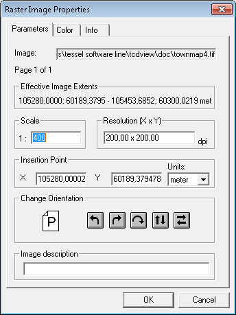
This command launches the Raster Drawing Parameters dialog box (or Vector Drawing Parameters, depending on the current drawing type),
which allows to edit technical parameters of the selected drawing.
The Raster Drawing Parameters dialog box is a tabbed dialog. It can have from one up to three pages. The page titled Parameters is always present. The page titled Pages is present only when properties of multipage raster drawing are shown. The page titled Colors is present only when at least one drawing page is monochrome. On the Parameters page you can set the following:
Effective Drawing Extents- values calculated from the other parameters;Scale- it is possible to set the nominal scale of the document;Resolution X x Y- it is possible to set the nominal horizontal and vertical resolutions of the bitmap in dots per inch;Insertion Pointio- it is possible to enter the insertion point coordinates, i.e. world coordinates of the bottom left corner of the drawing;Unitsu- list box allowing to select units for the insertion point;Change orientation- it is possible to rotate the view of the drawing left, right, by 180 degrees or perform vertical or horizontal mirroring of the view;Colorc- pressing this button launches the Raster Color dialog box; color can be defined only for monochromatic raster drawings;Drawing Description- it is possible to add textual document description.
On the Pages page you can select the current page of multipage raster drawing.
On the Colors page you can select color of monochrome raster drawing.
Vector Drawing Parameters dialog box is a tabbed dialog. It has two pages: Parameters and Layers. On the Parameters page you can set the following parameters:
Units- list box allowing to select units for the vector drawing;Change orientation- it is possible to rotate the view of specified drawing left, right, by 180 degrees or perform vertical or horizontal mirroring of the view;
On the Layers page it is possible to enable or disable displaying of particular layer of the vector drawing.
In the Change Orientation group of both drawing parameter dialogs there are icons with arrows describing available orientation changes.
To make orientation changes even simpler there is also an icon with the P character.
After entering the Drawing Parameters dialog box this icon shows the P character in normal orientation.
After pressing any of buttons with arrows, the P character rotates accordingly, thus showing how drawing will be rotated when the OK button is pressed.
The values of drawing parameters are saved in the drawing file, if the drawing format allows for it,
and in an additional parameter file with the same name as drawing file name but with TAF extension.
The additional file is located in the same disk directory as the drawing file.
The additional parameter file is necessary, because not every parameter can be saved in the original drawing file.
Some drawing file formats allow to store more parameters than other formats.
Parameters saved in the original drawing file override parameters saved in its additional parameter file.
Creation and reading of parameter files can be controlled using the BRAOpenOptions parameter in the TSLSV.INI file.
The parameter values are read from the drawing file and possibly from its parameter file. All of them can be changed, except for Drawing Extents that are calculated from other parameters. When any parameter has been changed, the drawing is considered changed, and SuperView asks the user for saving changes in a file, when it is about to be closed.
The Zoom menu commands are used for displaying selected fragments of documents and for magnifying or lessening the current view.
For each open document SuperView keeps a full view of this document.
This feature allows to execute the Zoom - Extents command very fast.
Full view cache is also used for other zooms, unless it decreases view quality too much.
The Regenerate command forces the full resolution redraw without using the intermediate stored view.
Storing and using of the full view cache can be disabled by setting the UseFullViewCache parameter in the TSLSV.INI file (see the section called “[TSLRVC Library Settings] section”).
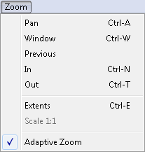
The Window command allows to define any rectangular view of a document.
After defining a rectangle, the raster area inside it is redisplayed according to a new scale, such that the selected area fills up the whole current document window.
View expansions in one direction, if necessary, are added automatically.
The Zoom-Window command is the default action when the user selects a rectangle in a document window,
so it is not necessary to invoke this command directly to execute it - selecting a rectangle to be viewed with the mouse is enough.
The Previous command displays the previously defined view of the current document (if such a view exists). The maximal number of remembered views is 15.
The In command magnifies the current view (approximately two times) relatively to its center point. The view will present a smaller document area but will contain more details.
The Out command increases the area covered by the current view (approximately two times) relatively to its center point. The view will present a larger document area but will contain less details.
The Extents command is used to display the view of the whole current document (by magnifying or lessening its view), so that it fills up possibly largest part of its full window.
The Scale 1:1 command is used to view a single drawing document on the screen in its original physical dimensions. When the current composite document contains more than one drawing, this command is not available.
In this command the vector or raster data is displayed on the screen in such a way, that one inch on the screen is equivalent to one inch on the paper document original (with maximal possible accuracy).
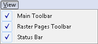
The View menu contains commands to activate and deactivate Toolbar and Status Bar.
The Main Toolbar command toggles the display status (visible/invisible) of the main toolbar,
which is on the top of the main SuperView window, just below the main menu bar.

If this option is switched on - what is indicated by the presence of a marker before the command name in the View menu - then the toolbar is displayed and through icons displayed on itself allows for fast access to the most frequently used SuperView commands. The verbal description of commands available through the toolbar is displayed on the status bar, when the left mouse button is press and held with the cursor over a toolbar icon. Switching the Toolbar option off by clicking on its name in the View menu results in disappearing of the toolbar. The next click on the option name switches the option and the toolbar on.
This command toggles the display status (visible/invisible) of Raster Toolbar which is just next to Main Toolbar.
The Status Bar command toggles the display state (visible/invisible) of the status bar (see the Windows and menus layout section), which is located at the bottom of the main SuperView window.

If this option is switched on - what is indicated by the presence of a marker before the command name in the View menu - then the status bar is displayed,
presenting in its left part the verbal description of the command currently being selected from the application menu or from the toolbar.
Library procedures also display its messages on the status bar - mostly with percentages of progress of their complex operations.
The Measure Distance command from the Options menu displays its results on the left side of the status bar.
There are three information windows on the right side of the status bar. They are used to display (from left to right):
the first window is filled only in selecting state - when one component drawing is selected, its name is displayed, when two or more drawings are selected, their number is displayed (e.g.: “Sel: 2 of 4”);
current coordinates of the mouse cursor in the world coordinate system of the composite document displayed in the current window;
presentation units of the document displayed in the current window; mouse cursor coordinates are expressed in these units.
Switching the Status Bar option off by clicking on its name in the View menu results in disappearing of the status bar. The next click on the option name switches the option and the status bar on.
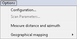
The Options menu commands can be used to set some parameters of the current scanner and to measure distance (in the real world units) between points of the current document.
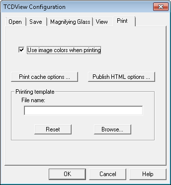
The Configuration command opens SuperView Configuration dialog where you can configure SuperView program. The dialog consists of 5 tabs:
Open, Save, Magnifying Glass, View, Print.
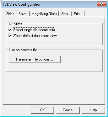
The Open tab allows you to configure options that control opening SuperView files:
Select single file documents
If this option is checked SuperView automatically selects a single image file, or a
TCDfile with only one subdocument, immediately after the open operation. This option corresponds to the AutoSelectSingleFile parameter from the[TSLRVC Library Settings]section in theTSLSV.INIfile.Zoom default document view
If this option is checked, immediately after opening a raster image or a composite document SuperView uses default view parameters.
The Parameters file options… button invokes the External Parameters File Options dialog that lets you set options and priority of particular file formats.
The parameter values are read from the image file and possibly from its attribute file.
All of them can be changed, except for the Effective Image Extents that are calculated from other parameters.
When any parameter has been changed, the image is considered as changed, and SuperView asks the user for saving changes in a file, when it is about to be closed.
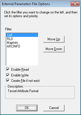
You can specify the following options for each parameter file format:
Enable to Read
if selected SuperView tries to find parameters file corresponding to currently opened image and read missing parameters,
Enable to Write
if selected SuperView tries to find parameters file corresponding to currently saved image and write new parameters values,
Create file if not exists
Create file if not exists – Accessible only when Enable to write is selected. Controls whether a file in this format should be created if it does not exist.
Additionally you can define parameter file priority by sorting them in the list.
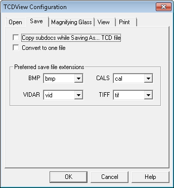
The Save tab allows you to defining the following options:
Copy subdocs while Saving As... TCD file
If this option is checked SuperView saves not only TCD file with links to raster images or vector drawings, but also copy all subdocuments to new files. This option corresponds to the
TCDSaveModeparameter from the[TSLRVC Library Settings]section in the TSLSV.INI file.Convert to one file
If option is selected SuperView creates the multi-page destination file while converting multiple input files.
Preferred save file extension
Some raster formats may be saved under different file extensions. These include Tiff, Vidar, CALS and Bitmap. You can define preferred extension for each format.
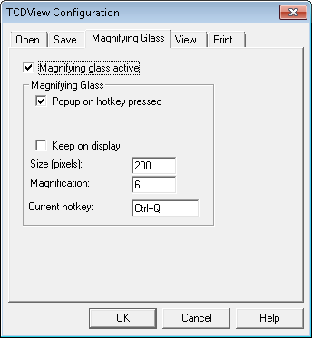
The Magnifying Glass tab allows you to configure the Magnifying Glass tool. Checking Magnifying Glass active box activates the function. When the Magnifying Glass window is displayed, you see a zoomed raster area around the position of the mouse pointer (the AutoCAD’s cross-hair) at the moment of the Magnifying Glass activation. If raster snap was active and successful, its result will be indicated by a cross symbol. If the snap result is not satisfactory, you may pick a new point precisely. The Keep on display option controls the method of closing the Magnifying Glass window. If option is not selected the Magnifying Glass window is closed automatically if you move the mouse cursor outside the window or you pick a new point inside the window. Otherwise the Magnifying Glass window disappears after pressing the Esc key or right mouse click. The Esc key cancels the point in the Magnifying Glass window.
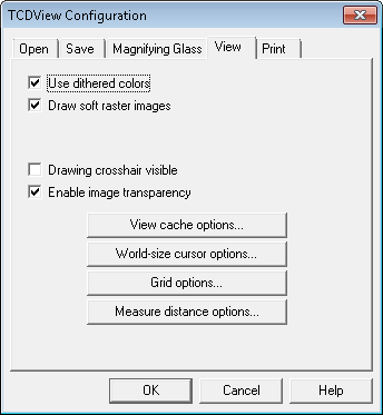
The View tab allows you to define view options:
Use dithered colors
If this option is checked SuperView uses dithering to improve image colors mapping. The option is especially useful when displaying images with a lot of colors on display devices with only 16 or 256 physical colors. This option corresponds to the DitherMode parameter from the
[TSLRVC Library Settings]section in the TSLSV.INI file.Enable image transparency
This option is responsible for switching on or off the usage of transparency information defined in a raster image.
The View cache options or Print cache options buttons invoke configuration dialogs of SuperView’s integrated view and print cache. All modified parameters are stored in the TSLSV.INI file. More information about modified property is specified in appendix.
The Scan Parameters... command launches a dialog box which allows to set technical parameters of the scanning process.
This dialog box depends on the current scanner type and is displayed and managed by its driver.
The parameters are specific for the particular type of the scanner that is currently used.
After setting parameter values one must initialize the scanning process.
Note
Saving the parameter values is done during scanning. That is why in order to save parameters, one must perform “dummy” scanning - it is not enough just to set parameters up.
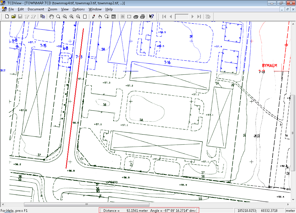
The Measure and azimuth distance command expects you to click the mouse left button at two points of the current document area.
It then displays the real world (not paper document) distance between these points and angle of created line against the p on center of the status bar.
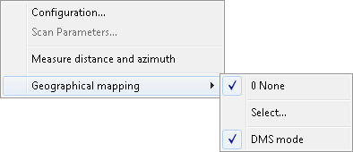
The OTM Geographical Mapping sub-menu is checked when some geographical mapping is active. The sub-menu of the Geographical Mapping option consists of the items described below.
0 NoneIf the 0 None option is set, SuperView does not use geographical mapping at all. The check mark placed at the None option indicates that no mapping is active. The coordinate system and units used in this case are determined by settings of the coordinate system and presentation units combo boxes on the Input bar;
1, 2, 3, 4 RecentUse Recent option to select one of the geographical mapping systems recently used. Names of these mappings are listed on subsequent items of sub-menu. The check mark placed at the mapping name indicates that this mapping is active. SuperView remembers up to four mappings. They are numbered from one up to four (zero is reserved to None mapping option item). The order of mapping system sequence on the sub-menu matches the selection history. The absence of Recent items suggests that geographical mapping has not been used in the configuration taken from the TSLSV.INI file. The check mark placed at the mapping name indicates that this mapping is active. The names and the order of mappings are saved in the TSLSV.INI configuration file and set automatically after starting the application again;
Select...Use Select...option to set the current geographical mapping system. After entering the option, the Geographical Mapping dialog is displayed. The chosen mapping becomes the current one. It means that all entered, displayed and edited coordinates are interpreted using the current mapping. Its name is displayed on sub-menu as Recent mapping item and checked.
The Geographical Mapping dialog
consists of the listbox with names of geographical mapping systems
supported by TSLGEO32.DLL (see Geographical Mapping Systems
in the section called “[Geographical Mappings] section”). The name and description of selected mapping are
displayed in Mapping Name and
Mapping Description boxes.
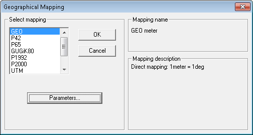
Activate Parameters... button to set parameters of selected mapping by means of additional dialog box. A content of the dialog depends on the mapping. The button is disabled if the chosen system is not configurable (it has no changeable parameters).
Use OK button to accept the selected mapping and close the dialog. Use Cancel button to withdraw changes made (if any) and close the dialog.
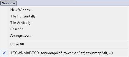
The purpose of the Window menu commands is to change the layout of open document windows.
The third part of this menu displays a list of open document names.
These names are equivalent to document window names, which allows to select a new current (active) window.
This is necessary, since the required window may be completely covered by other windows.
The current window is marked in the menu with a check marker.
The New Window command opens a new window with the current document.
The next ordinal number of the window (opened with the same composite document as the previous current window) is displayed on the title bar of this window to the right of the file name(s).
When more than one document window is open, the Tile Horizontally command divides the whole SuperView main window between all equally sized document windows.
When just one document is open, its window is expanded to fill the entire SuperView main window.
As a result of this command, open document windows are arranged in such a way, that each is visible and does not overlap with any of the other windows and the neighbouring windows have common horizontal borders.
When more than one document window is open, the Tile Vertically command divides the whole SuperView main window between all equally sized document windows.
When just one document is open, its window is expanded to fill the entire SuperView main window.
As a result of this command, open document windows are arranged in such a way, that each is visible and does not overlap with any of the other windows and the neighbouring windows have common vertical borders.
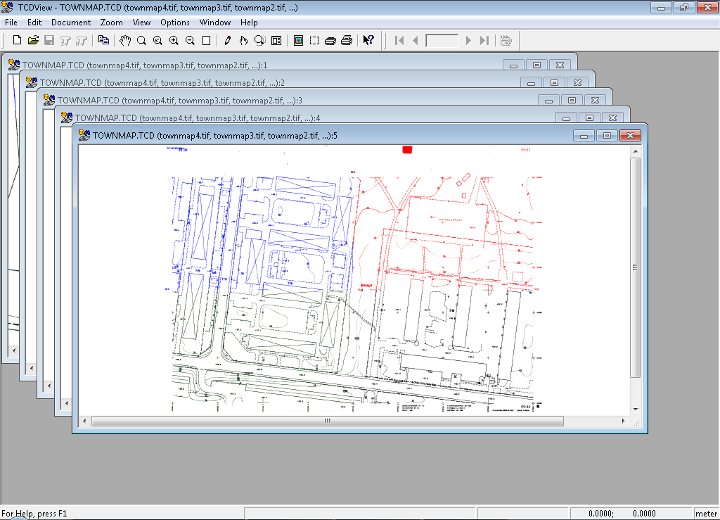
When more than one document window is open, the Cascade command arranges open document windows on the main SuperView window in such a way,
that they overlap and form a kind of stack but each is shifted a little, so that their title bars are visible.
The current document window remains active and is put on the top of the stack of document windows.
When just one document is open, its window is expanded to fill the entire SuperView main window.
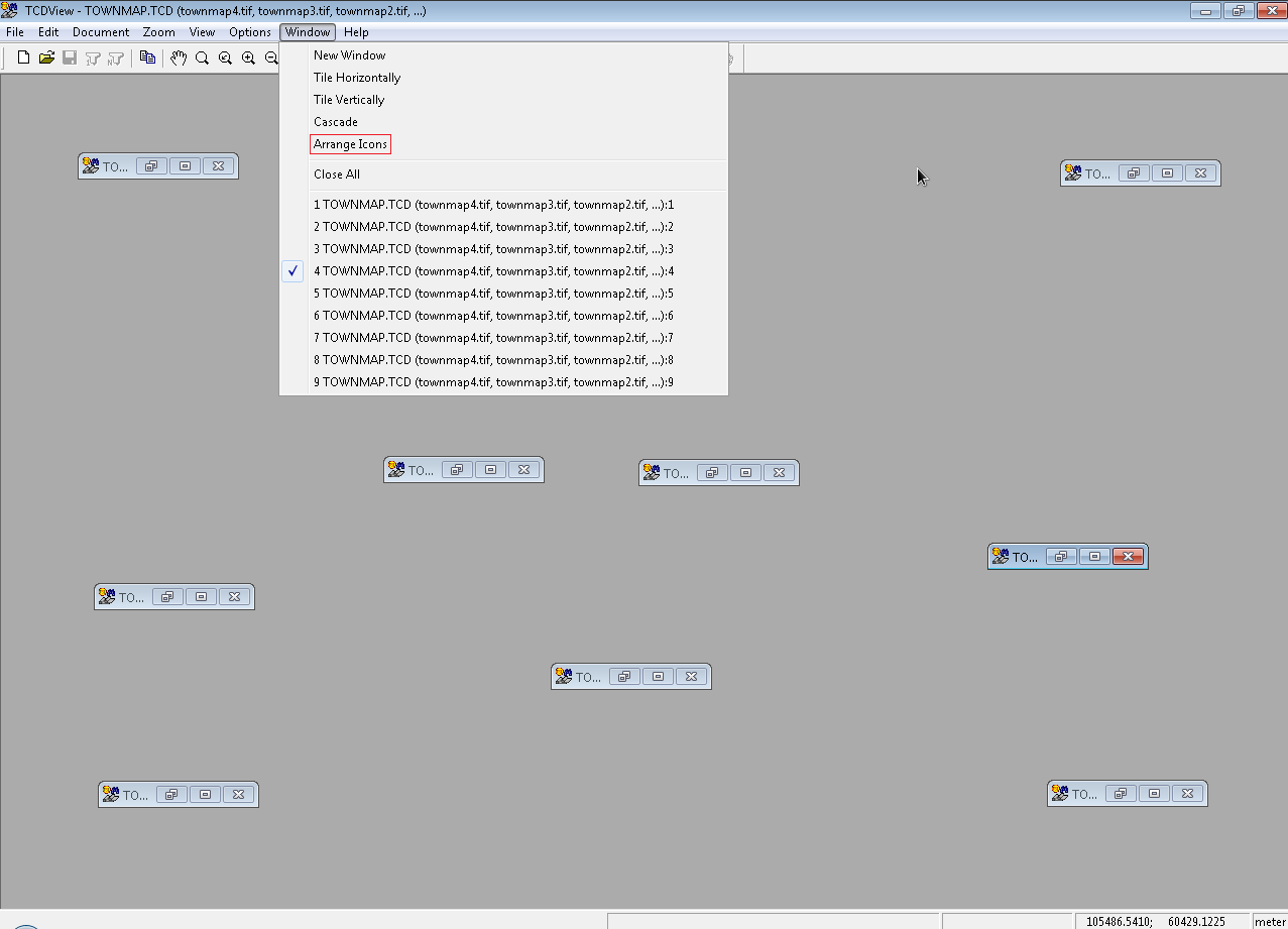
Every document window can be minimized to a form of a SuperView icon labelled with a document name.
The names of minimized windows (documents) remain present on the list of open documents in the Window menu.
These icons can be dragged with the mouse one by one to a new place.
The Arrange Icons command changes the placement of this icons.
It puts them in a row(s) at the bottom of the main SuperView window.
When you double click with a mouse on a document icon or click on a document name on the list in the Window menu, the selected document window opens again at the previous place and size.
The Arrange Icons command does not move open windows, so they may overlap the area, where document icons are placed.
In such a situation you can uncover the icons by resizing the windows manually or with the Cascade command.
